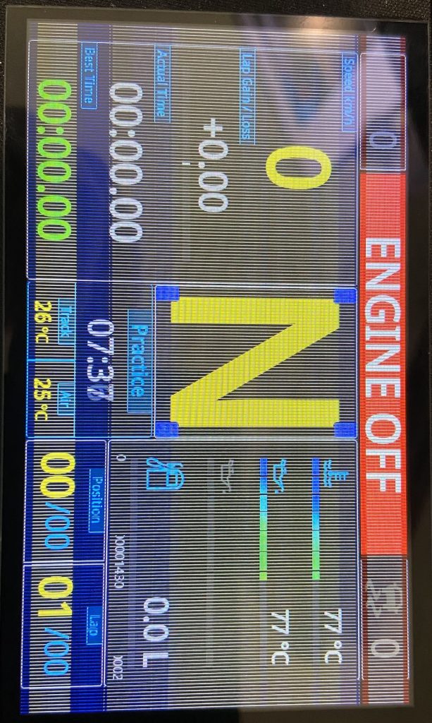
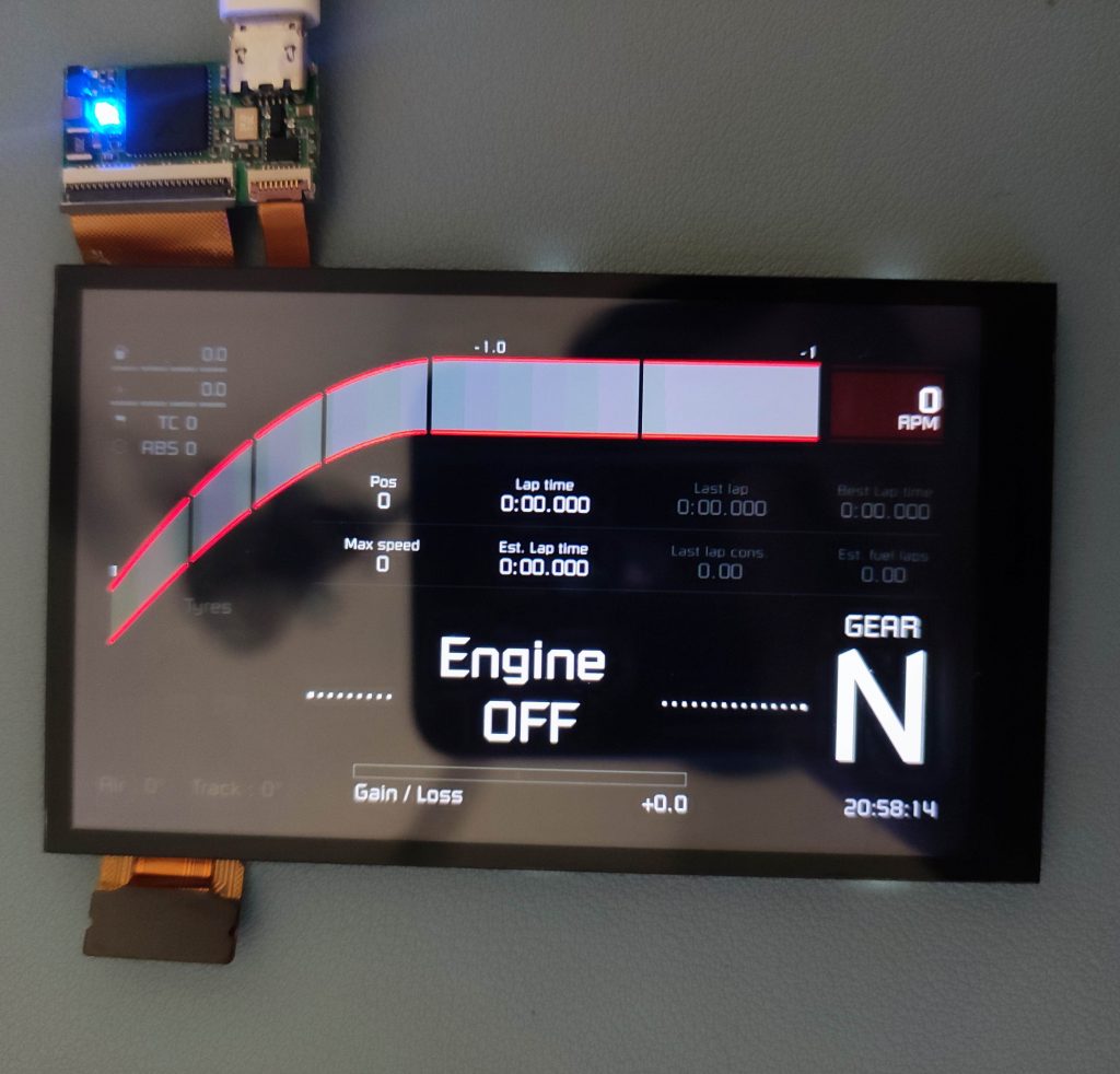
Recently we get report about some screens are broken. The bad one looks like this:
On some screens, white lines appear across the whole display.On some types of screens, if there’s only a small crack, the line may disappear over time—but it reappears when displaying rapidly changing images.
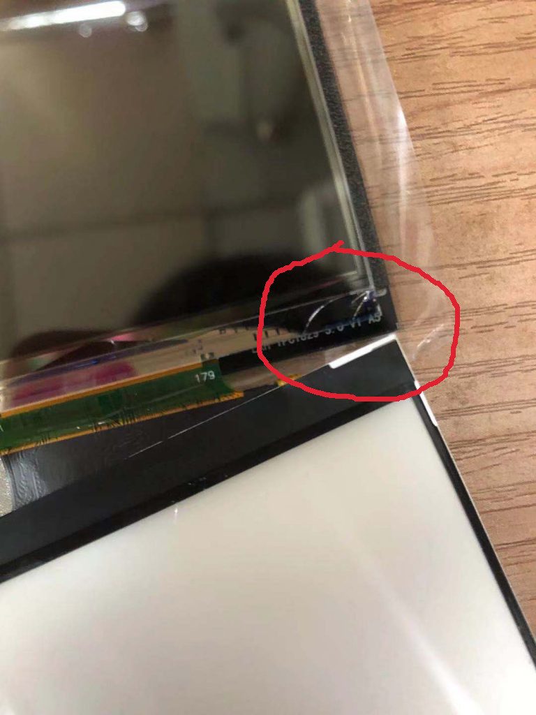
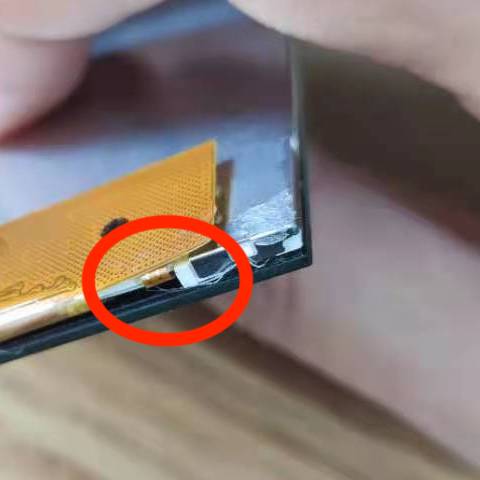
It shows some unexpected line on screen. When we get the returned screen, and find under touch screen the display glass corner is broken…
The glass on the red circuit is cracked. It’s super easy to break if you press on a corner—even a tiny crack can be serious. You’ll only notice it if you look at just the right angle with strong lighting.
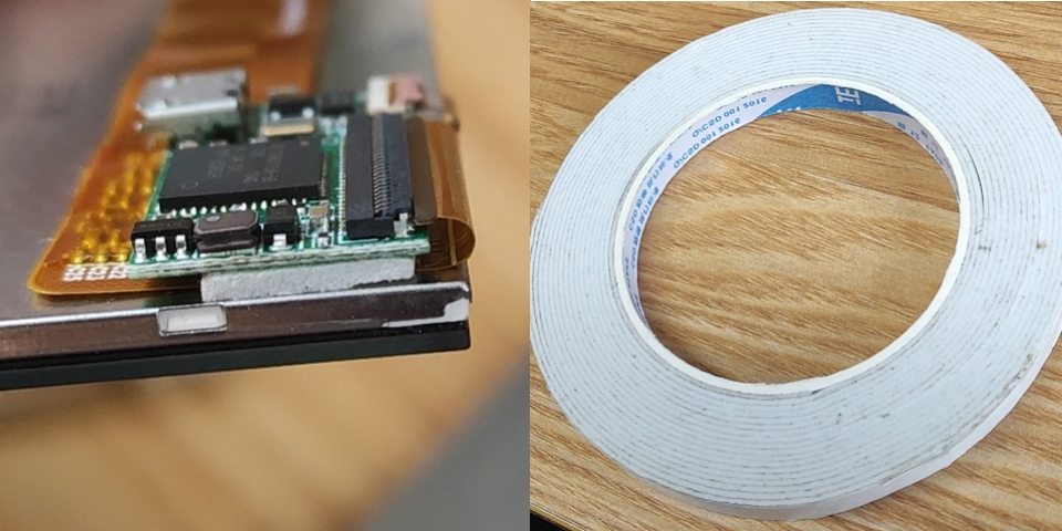
From the picture, I find its inside chip is so thin, and looks like made by glass, I think it should be Silicon, used to driver every line on the screen 🙂
For DIYer, please be very careful when install this part, only 0.2mm so it can not stand any force. We will also be very careful when package them.
The glass corner is fragile, here are some bad examples..
Because current 4inch screen(based on driver board v10a) is designed for very low power usage and intend to be long life time, so we have to limit its backlight brightness to save power. But currently maybe people do not care about the power usage and backlight lifetime, so I write this blog to provide a solution.
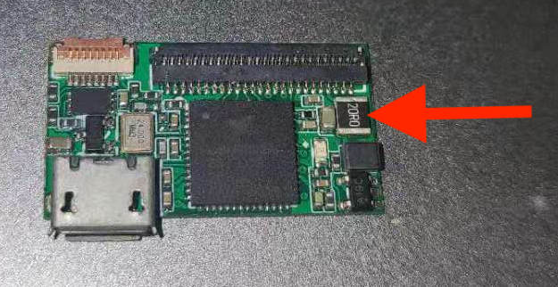
v10a driver board has a 1210 size resistor, normally on its top marked 20R0 or 200. It is 20ohm resistor(red arrow).
v10a version
Change that 20ohm resistor to 1ohm resistor will be able to make it brightness to max, and its output current will be 160mA. Do not use smaller than 1ohm resistor, backlight will burn in a short time… and do not ask me how I know that. :’) 160mA should be its max safe current for 1~2 year usage — I did not test.
After the modify, it will be much brighter than the original version. But any magic has a cost, this will reduce 75% LED life time and much increase power consume, the driver board will become pretty hot, from my test, increase around 15C, current consume from 0.12w to 0.25w.
PS: this modification is not easy for beginner, need a hot air gun and some glue, if action not careful enough, might melt the connector, DIY is always dangerous, be careful 🙂
5inch(v7a) also has a way to increase brightness, need to change one resistor from 10ohm to 5ohm to double its current. From my test, it do not have big difference, not worth to do the change.
Recently chip price is even crazy. Our screen main chip price increased 60%…and screen driver chip price increased 100%.
We have to increase VoCore2 4inch Screen price from 35.99USD to 37.99USD, 5inch Screen from 52.99USD to 53.99USD in order to cover the crazy increased cost more or less.
We promise once chip price back to normal, we will reduce the price to normal too. Sorry about this, hopefully this crazy chip shortage will end soon.
Update 20230222: SimHub WinUSB driver link https://simhubdash.com/Drivers/VOCOREScreenSetup.exe
Update 20220604: Please use zadig to install libusb driver, new tutorial here http://vonger.cn/?p=15204 or use WinUSB driver from SimHub. They are much stable than libusbK driver.
Recently everyday we get a lot of emails about screen can not work after USB plugin. I have to write this tutorial as people said there is no tutorial …
PS: I think this should be Simhub developer job? 🙂
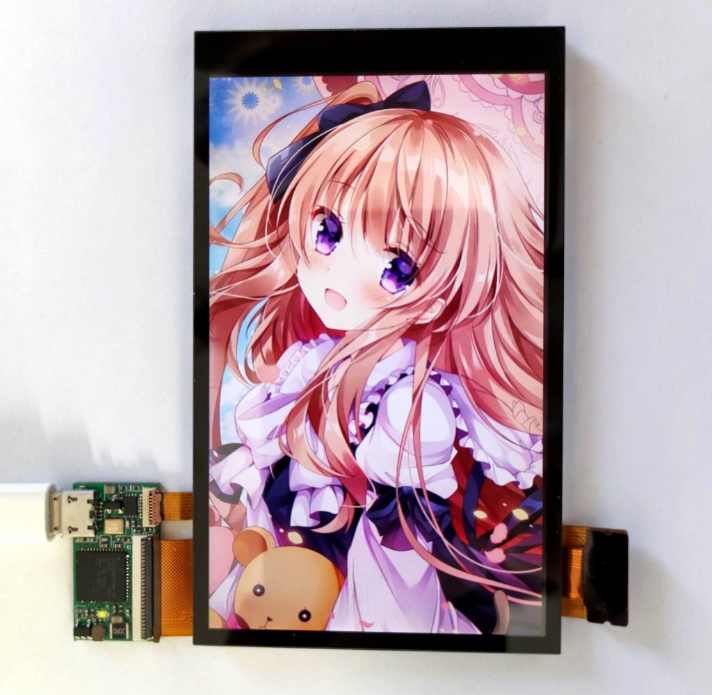
First of first, plugin the microUSB cable to screen and another side to the computer. VoCore Screen requires a very good USB cable, because it will send data at max USB 2.0 speed, over 300MHz, even faster than most DDR data line.
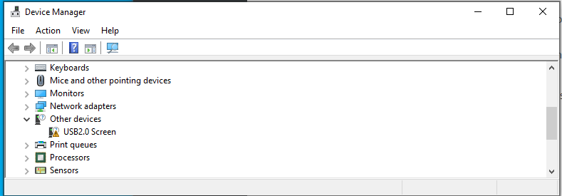
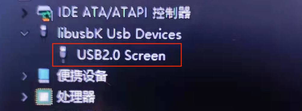
You will find the screen in your device manager, means it is connected.
USB2.0 Screen is our VoCore Screen
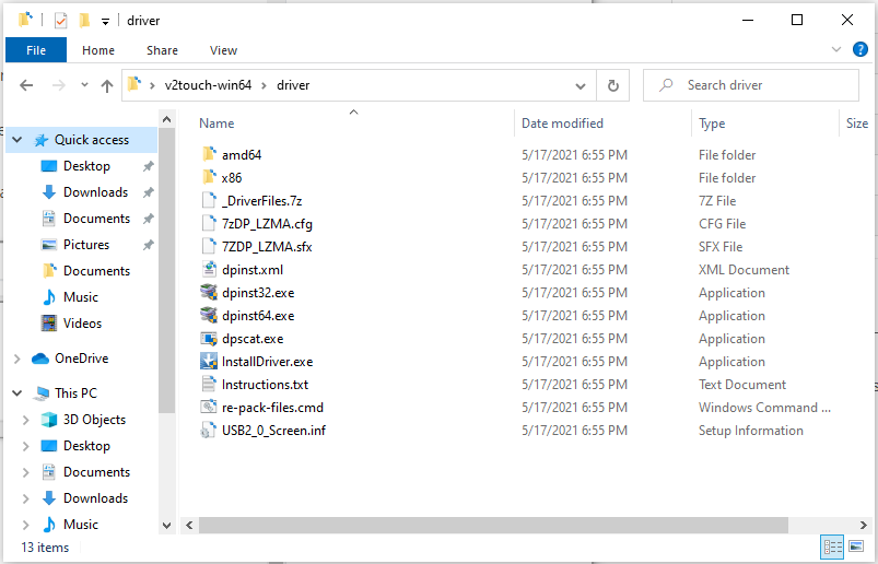
Next, let’s install its driver. Download it here: http://vonger.cn/misc/screen/v2touch-win64.zip
run InstallDriver.exe
Uncompress the zip file, and run InstallDriver.exe in its driver folder.
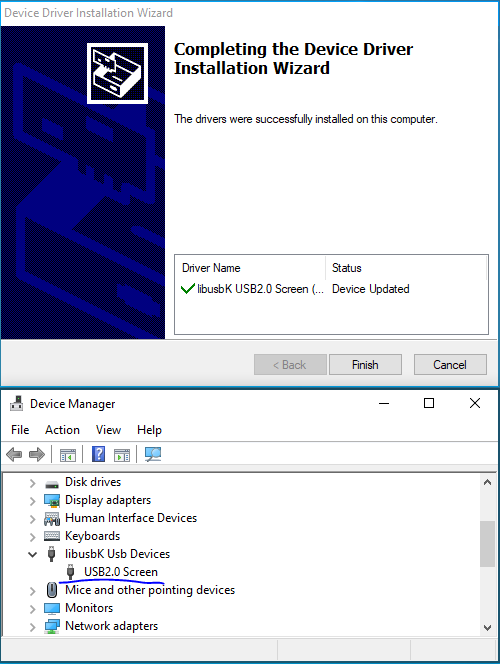
a few seconds, install completed
After install completed, you will find the device is working now. Under libusbK Usb Device => USB2.0 Screen
Test, now everything is ready, we can run screen_test.exe in the driver package, check if the screen is able to show something, also screen_test can be used to check if touch screen is working normal.
Final, run SimHub
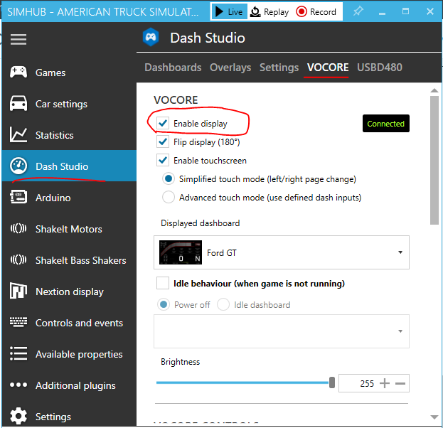
You will need to enable VoCore Screen first.
Click on Dashboard => VoCore => Enable display, once it shows connected, in a few seconds you will see the dashboard show in VoCore Screen.
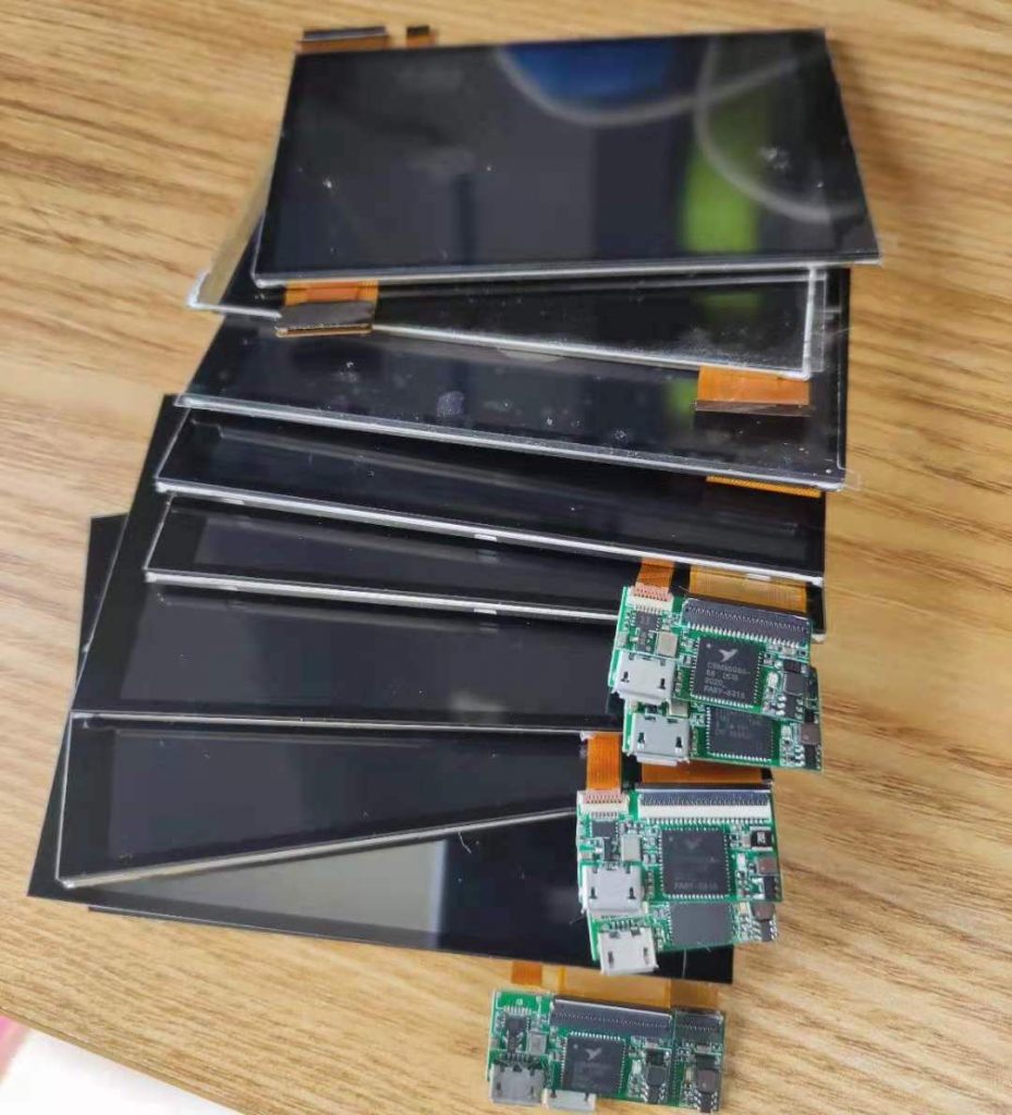
Recently I get around 10pcs broken ones returned. Is it really the mystery ESD problem or something else? Let’s analyze one by one check what is the problem. Hopefully this blog will also help DIYer find a way to solve such problem.
some broken screens.
1.Obvious physics broken ones:
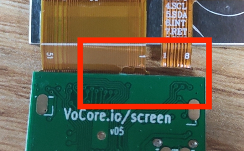
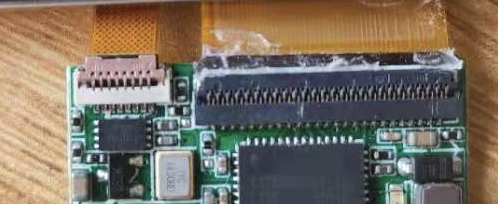
Four screens has such problem. Red rectangle area is the weak point.
Left FPC 51p is for screen and right 8p is for touch screen. From the picture, the 51p and 8p both tear off by force. FPC is something like tape, it is afraid of sharp edge. Such problem normally happens when you bend the FPC hard, and FPC touch the PCB or the connector edge, it will be easily broken.
Recommend: FPC better to have a beautiful round corner, this will reduce tear off chance, also use the bubble tape around 1mm to stick it to PCB or back, NOT recommend use the hot melt adhesive, it is bad to fix the PCB because there are so less margin after it becomes solid, that will cause it easy to broken FPC.
2. Hidden Physics Broken
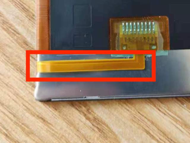
This screen problem is when we run test application send_frame frame.dat, its backlight will not able to turn on. One of broken screen is such problem. After remove its touch screen, I find the FPC is normal, but the liquid crystal driver chip is shattered. That driver chip is like a very thin glass, and when people is trying to force the glue on FPC off its holder, it will have very high chance to broken that chip.
PS: this part debug is a pain, last year on another project we use this screen, around 20pcs broken because of such problem, workers mistake stick the bubble tape to this area so when we remove the screen to repair other parts the screen broken by the force.
Recommend: tape or adhesive leave far away from this area! Do not touch this FPC at install. New version screen do not have such problem, but we still suggestion do not put any tape or adhesive on the FPC area, it should be only on the steel part.
3. Not Well Connected
adhesive inside connector, caused it not well connected.
One broken because of this reason, this screen also has FPC tear off problem.
Recommend: please do not use adhesive… 🙁
4. Firmware Problem
Rest screens are all such problem. This problem I never expected. That just is the unknown device problem. This should not happen if the screen is operated normally, I guess maybe some client side code has bug, I will check with SimHub developer.
For my MacOS or Linux, we have lsusb command, it will show the device like this:
Bus 020 Device 005: ID 04b4:8613 Cypress Semiconductor Vendor-Specific Device
If firmware is normal, it should be like this:
Bus 020 Device 011: ID c872:1004 c872 USB2.0 Screen
The firmware is written in EEPROM, and it should never lost any data unless client side application write something wrong to it…This is very weird.
I attached the firmware loader(download here), this application only run in MacOS.
For PCB version v05 and v07a, please call
./eeprom w ./FW200502-4IN14V.bin
For PCB version v10a, please call
./eeprom w ./FW210105-4IN3V3
After firmware upload completed, disconnect and reconnect the USB cable, all of the screens has such problem are fixed.
So the final result, none of the driver board are really broken 🙂 Just the physics broken screen we can not fix have to change screen. All 10 of them are repaired.
5. USB cable problem
This is not belong to this part but also very important, please use a short or well covered USB cable. This screen used max USB speed, every data line is 480MHz, so a bad quality USB cable will not make it work, will cause sometimes the screen can not be recognized or show some random noise on the screen. We also think the firmware is broken by this way. This need to be confirm.
Recently some people report to us one problem. After they power on computer, VoCore Screen can not be found anymore, it become an Unknown Device. Currently the bad ones are on their way shipping back to us, but for now, I think I can guess what is the problem already.
It is a very weird issue, because our screen is already in some projects and pretty stable for two years, should it be the chip become bad for this batch?
Interesting thing is our embed users never report such problem but only PC users who using the screen as an extend screen run SimHub has such problem.
So, it can not be the chip problem…If there are some problem, it must be ESD!
The critical problem should be the USB data line do not have TVS diode protected. And USB data line is weak to strong noise, strong EMI will broken it from inside. But where is the noise from?
After a lot of check with the client, the truth comes up. Normally Simhub users are using a very powerful PC who has a big power supply, some times the user will open the PC metal enclosure for better cooler, then the room become a hell of the screen driver board… because it do not have any protect. :'(
I have to say it is my design flaw, this screen is designed for VoCore2, it is not designed to use in such situation. Normally for embed usage, the USB cable is very short and well protected by ground, it is not necessary to use TVS diode to protect the USB. But PC…ahhhh, PC is another story.
OK, let’s talk something hardcore…
Solution for current version
PS: I know it is stupid…but in order to increase the board life, it is necessary
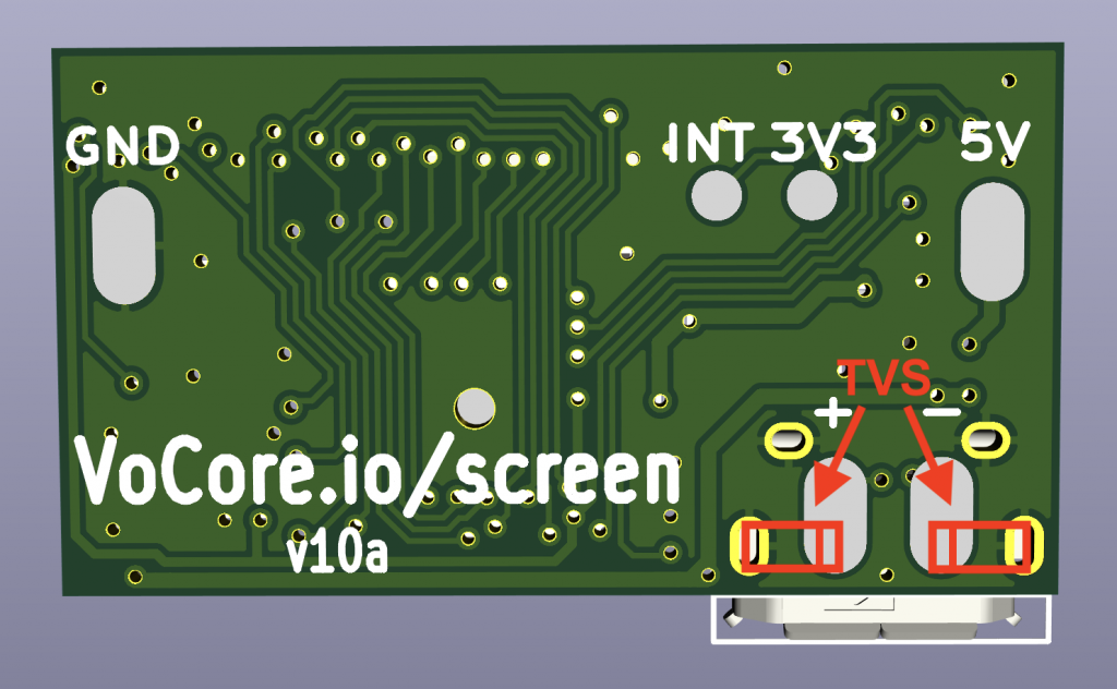
solder two TVS diodes to the USB cable D+/D-.
add two USB TVS diodes to red box
connect the screen after you power on your desktop PC.
cover the EMI source with metal case, to reduce the power on/off ; noise. (noise mainly from power on)
a well protected/short USB cable also work.
Note: TVS diode capacitance should be < 3pF, voltage 3.3V or 5V.
Any of the three way will work.
New screen shipped from Mar.25 will default have the protect diode solder on bottom side.
Update: we finally get some broken samples…but none of them are broken by ESD, all broken by force install caused PCB bend, chip is not connected well to PCB.
Update: v7a/v10a driver board is designed for embed device, not test on PC. From Oct.1, 2021, we have v7b/v10b version, special optimize for PC, fixed such problem.
Source code of fbusb link: https://github.com/Vonger/vocore2/tree/master/utils/fbusb
Directly Compile in Linux(raspberry pi)
This is tested on raspberrypi, it should be also working on another Linux system. Please go to fbusb/src folder then run this command.
make -C /usr/src/linux-headers-$(uname -r ) M=$PWD modules
After this command, you will get fbusb.ko
Cross-Compile for OpenWrt in MacOS
Cross compile is similar. For example, I want to compile the driver for the VoCore on my Macbook, I will need to go to fbusb driver folder first, then run this command:
make -C /Volumes/OpenWrt/build_dir/target-mipsel_24kc_musl/linux-ramips_mt76x8/linux-4.14.195 M=$(PWD) CROSS_COMPILE=mipsel-openwrt-linux- ARCH=mips
This path /Volumes/OpenWrt/build_dir/target-mipsel_24kc_musl/linux-ramips_mt76x8/linux-4.14.195 is my Linux header path, You need to change it to yours.
VoCore Screen is mainly designed for embed Linux, so it is easy to work on Linux or Unix(MacOS), but for windows, it is not that smooth. Windows do not have libusb support directly, so we have to use third party driver to achieve that, like libusbK.
Recently pretty much people use this screen for car race simulator on Windows, so I think it is necessary for me to write a tutorial to show how to fast test if the screen work normal under Windows OS.
First, we need install libusbK for Windows
We already have it in our windows SDK, you can download it at vocore.io/screen.html, or use this directly link here: http://vonger.cn/misc/screen/v2touch-win64.zip, uncompress it and install the libusbK driver, you can find the device “USB 2.0 Screen” at your “Device Manager”.
Second, try our new test app in SDK.
In v2touch-win64.zip, there is one folder named example, used to test the screen.
And we have a test data, frame.dat. So we can directly run send_frame in the example folder in windows command line.
send_frame frame.dat
Then your screen will display the test picture. Test picture should be 480×800 size and 16bit RGB format BMP, remove 139 byte BITMAP header, raw data.
Other Commands Usage
send_frame
usage: send_frame [frame data file]
used to send one frame(bmp 16bit format data without bitmap header) to screen.
example: send_frame frame.dat
read_touch
usage: read_touch
used to read touch screen position and press status, no parameter.
send_cmd
usage: send_cmd [cmd] [param]
used to send command to screen, control screen rotated or backlight.
example: mirror by axis x,y [0,1,2,3] to mode1 send_cmd m 1
example: set backlight [0~255] to 120 send_cmd b 120
From last year Sep.1, we meet global chip shortage. Recently some chips price increase to incredible level. My chip provider told me, currently STM32F103 price is around 72CNY/pcs(11USD/pcs) compare to early of last year only 3~5CNY. Another network chip IP101G, from 0.8~1CNY to 10CNY. 🙁 This is really crazy.
PS: Lucky, I use Gigadevice MCU, pin to pin STM32 but need to recompile firmware. Its price increased 10%~15%, compare to STM32 chip, looks like it is reasonable and acceptable.
For our production VoCore2 and camera, we have enough stock, but screen driver chip now have problem. The chip factory give me 25~30 weeks lead time, that is over half year. We have to change current screen plan.
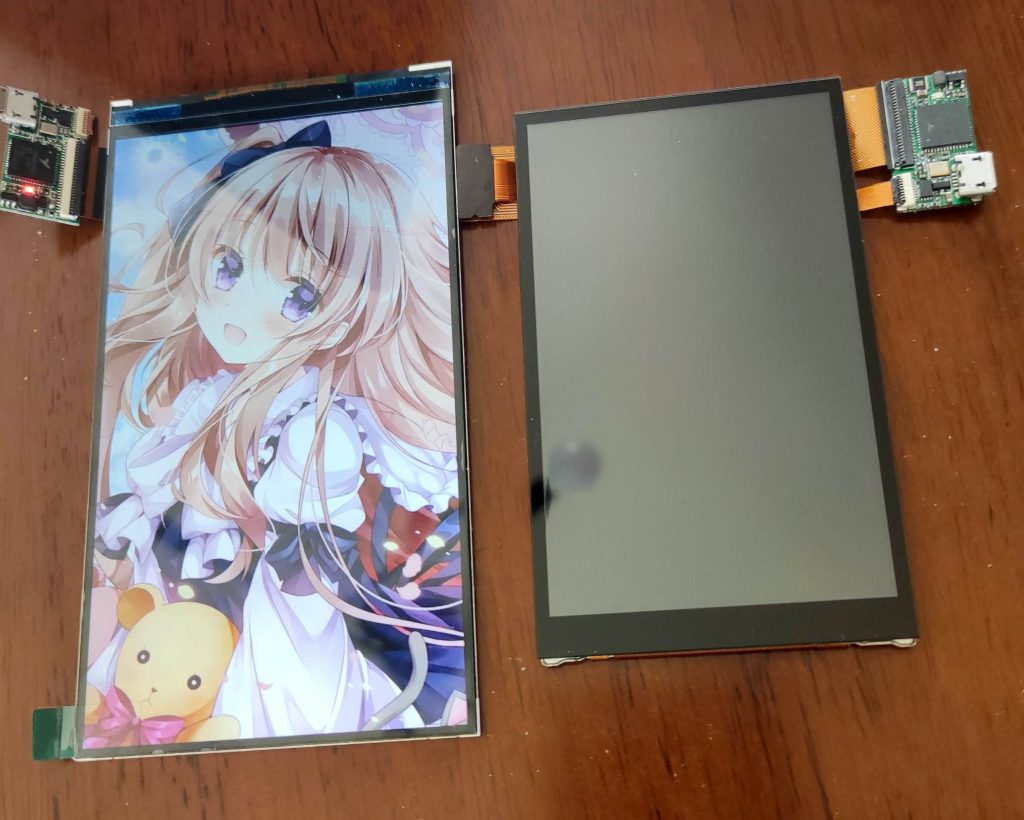
New screen is from Toshiba, better color than our old one. In order to compatible with old design, we add a FPC to convert its connector. For order later than Feb.9, we will all ship this screen. In software level they are compatible.
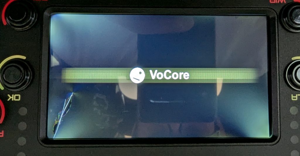
One slight difference, old screen once power on will show a white screen, this new one show black screen as default.
Screen size is almost same as old version(around 0.5mm smaller for both sides) also FPC is bendable, so this design should be compatible to most old screen enclosure.