This is the first version of the firmware
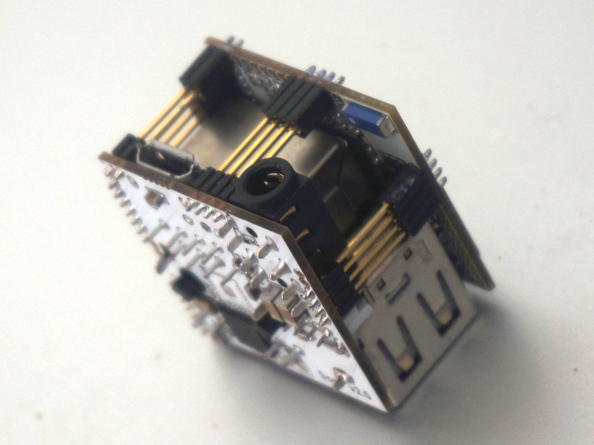
This firmware is only for dock2(with WM8960 chip at bottom)
Download at
http://vonger.cn/upload/firmware/vocore.dock2.bin
Compile by yourself:
1. clone openwrt 14.07 to your linux pc or vm.
git clone git://git.openwrt.org/14.07/openwrt.git
2. update VOCORE.dts, the following one is mine.
/dts-v1/;

/include/ "rt5350.dtsi"

/ {
	compatible = "VoCore", "ralink,rt5350-soc";
	model = "VoCore";

	palmbus@10000000 {
		gpio1: gpio@660 {
			status = "okay";
		};

		spi@b00 {
			status = "okay";

			m25p80@0 {
				#address-cells = <1>;
				#size-cells = <1>;
				compatible = "s25fl064k";
				reg = <0>;
				linux,modalias = "m25p80", "s25fl064k";
				spi-max-frequency = <10000000>;

				partition@0 {
					label = "uboot";
					reg = <0x0 0x30000>;
					read-only;
				};

				partition@30000 {
					label = "uboot-env";
					reg = <0x30000 0x10000>;
					read-only;
				};

				factory: partition@40000 {
					label = "factory";
					reg = <0x40000 0x10000>;
					read-only;
				};

				partition@50000 {
					label = "firmware";
					reg = <0x50000 0xfb0000>;
				};
			};

			spidev@1 {
				compatible = "linux,spidev";
				spi-max-frequency = <10000000>;
				reg = <1>;
			};
		};

                gdma: gdma@2800 {
                        compatible = "ralink,rt2880-gdma";
                        reg = <0x2800 0x800>;

                        resets = <&rstctrl 14>;
                        reset-names = "dma";

                        interrupt-parent = <&intc>;
                        interrupts = <7>;

			#dma-cells = <1>;
			#dma-channels = <16>;
			#dma-requests = <8>;
                };

		i2s: i2s@a00 {
			compatible = "ralink,mt7620a-i2s";
			reg = <0xa00 0x100>;

			resets = <&rstctrl 17>;
			reset-names = "i2s";

			interrupt-parent = <&intc>;
			interrupts = <10>;

			dmas = <&gdma 2 &gdma 3>;
			dma-names = "tx", "rx";
		};
	};

	pinctrl {
		state_default: pinctrl0 {
			gpio {
				ralink,group = "jtag", "led";
				ralink,function = "gpio";
			};

			gpio_i2s {
				ralink,group = "uartf";
				ralink,function = "gpio i2s";
			};
		};
	};

	ethernet@10100000 {
		mtd-mac-address = <&factory 0x4>;
	};

	esw@10110000 {
		ralink,portmap = <0x17>;
	};

	wmac@10180000 {
		ralink,mtd-eeprom = <&factory 0>;
	};

	ehci@101c0000 {
		status = "okay";
	};

	ohci@101c1000 {
		status = "okay";
	};

	i2c-gpio {
		compatible = "i2c-gpio";
		gpios = <&gpio0 11 0 &gpio0 14 0>;
		i2c-gpio,delay-us = <2>; /* around 400KHz */

		#address-cells = <1>;
		#size-cells = <0>;

		wm8960: wm8960@1a {
			compatible = "wm8960";
			reg = <0x1a>;
		};
	};

	audio {
		compatible = "ralink,wm8960-audio";
		model = "wm8960-audio";

		cpu-dai = <&i2s>;
		codec-dai = <&wm8960>;
	};

	gpio-export {
		compatible = "gpio-export";
		#size-cells = <0>;

		gpio0 {
			gpio-export,name = "gpio0";
			gpio-export,direction_may_change = <1>;
			gpios = <&gpio0 0 0>;
		};

		gpio12 {
			/* UARTF_DCD_N */
			gpio-export,name = "gpio12";
			gpio-export,direction_may_change = <1>;
			gpios = <&gpio0 12 0>;
		};
		gpio13 {
			/* UARTF_DSR_N */
			gpio-export,name = "gpio13";
			gpio-export,direction_may_change = <1>;
			gpios = <&gpio0 13 0>;
		};

		/* JTAG */
		gpio17 {
			/* JTAG_TDO */
			gpio-export,name = "gpio17";
			gpio-export,direction_may_change = <1>;
			gpios = <&gpio0 17 0>;
		};
		gpio18 {
			/* JTAG_TDI */
			gpio-export,name = "gpio18";
			gpio-export,direction_may_change = <1>;
			gpios = <&gpio0 18 0>;
		};
		gpio19 {
			/* JTAG_TMS */
			gpio-export,name = "gpio19";
			gpio-export,direction_may_change = <1>;
			gpios = <&gpio0 19 0>;
		};
		gpio20 {
			/* JTAG_TCLK */
			gpio-export,name = "gpio20";
			gpio-export,direction_may_change = <1>;
			gpios = <&gpio0 20 0>;
		};
		gpio21 {
			/* JTAG_TRST_N */
			gpio-export,name = "gpio21";
			gpio-export,direction_may_change = <1>;
			gpios = <&gpio0 21 0>;
		};

		/* ETH LEDs */
		gpio23 {
			/* ETH1_LED */
			gpio-export,name = "gpio23";
			gpio-export,direction_may_change = <1>;
			gpios = <&gpio1 1 0>;
		};
		gpio24 {
			/* ETH2_LED */
			gpio-export,name = "gpio24";
			gpio-export,direction_may_change = <1>;
			gpios = <&gpio1 2 0>;
		};
		gpio25 {
			/* ETH3_LED */
			gpio-export,name = "gpio25";
			gpio-export,direction_may_change = <1>;
			gpios = <&gpio1 3 0>;
		};
	};

	gpio-leds {
		compatible = "gpio-leds";
		status {
			label = "vocore:green:status";
			gpios = <&gpio1 0 0>;
		};
		eth {
			label = "vocore:orange:eth";
			gpios = <&gpio1 4 0>;
		};
	};
};
3. Setup dma driver, add dma.mk to [openwrt]/package/kernel/linux/modules/
DMA_MENU:=DMA support


define KernelPackage/ralink-gdma
  TITLE:=Ralink GDMA driver
  SUBMENU:=$(DMA_MENU)
  KCONFIG:= \
        CONFIG_DMADEVICES=y \
	CONFIG_DMA_ENGINE=y \
        CONFIG_DMA_VIRTUAL_CHANNELS \
        CONFIG_DMA_RALINK
  FILES:= \
        $(LINUX_DIR)/drivers/dma/virt-dma.ko \
        $(LINUX_DIR)/drivers/dma/ralink-gdma.ko
  AUTOLOAD:=$(call AutoLoad,11,ralink-gdma)
endef

define KernelPackage/ralink-gdma/description
 Kernel module for Ralink GDMA device support
endef

$(eval $(call KernelPackage,ralink-gdma))
4. Setup ALSA DMA
Whatever I do to the makefile/config, still two files can not be compiled, no idea what is wrong.
They are $LINUX/sound/soc/soc-dmaengine-pcm.c soc-generic-dmaengine-pcm.c
I have to force them to be compiled.
4.1. modify $LINUX/sound/Kconfig, comment that ifneq and endif.
#ifneq ($(CONFIG_SND_SOC_DMAENGINE_PCM),)
snd-soc-core-objs += soc-dmaengine-pcm.o
#endif

#ifneq ($(CONFIG_SND_SOC_GENERIC_DMAENGINE_PCM),)
snd-soc-core-objs += soc-generic-dmaengine-pcm.o
#endif
4.2. modify $OPENWRT/target/linux/ramips/rt305x/config-3.10 to force it compiled.
add two line at end of it.
CONFIG_SND_SOC_DMAENGINE_PCM=y
CONFIG_SND_SOC_GENERIC_DMAENGINE_PCM=y
5. Setup ALSA WM8960/I2S driver.
modify $OPENWRT/target/linux/ramips/modules.mk
@TARGET_ramips_mt7620a to @TARGET_ramips, so it will show not only MT7620a kernel but also in RT5350.
define KernelPackage/sound-mt7620
  TITLE:=MT7620 PCM/I2S Alsa Driver
  DEPENDS:=@TARGET_ramips +kmod-sound-soc-core +kmod-regmap
  KCONFIG:= \
        CONFIG_SND_MT7620_SOC_I2S \
        CONFIG_SND_MT7620_SOC_WM8960
  FILES:= \
        $(LINUX_DIR)/sound/soc/ralink/snd-soc-mt7620-i2s.ko \
        $(LINUX_DIR)/sound/soc/ralink/snd-soc-mt7620-wm8960.ko \
        $(LINUX_DIR)/sound/soc/codecs/snd-soc-wm8960.ko
  AUTOLOAD:=$(call AutoLoad,90,snd-soc-wm8960 snd-soc-mt7620-i2s snd-soc-mt7620-wm8960)
  $(call AddDepends/sound)
endef

define KernelPackage/sound-mt7620/description
 Alsa modules for ralink i2s controller.
endef

$(eval $(call KernelPackage,sound-mt7620))
6. Now, everything is ready. make menuconfig
Select in Kernel modules:
add I2C support/kmod-i2c-gpio-custom;
del I2C support/kmod-i2c-ralink;
add DMA support/kmod-ralink-gdma
add Sound support/kmod-sound-mt7620
7. That’s all, make V=s, build the bin file.
Later I will do more test on this firmware, dma, i2c and i2s works well in this firmware.
Drivers works:
root@OpenWrt:/dev# ls
audio               i2c-0               mtd0ro              mtd3ro              mtdblock1           network_throughput  shm                 urandom
bus                 kmsg                mtd1                mtd4                mtdblock2           null                snd                 watchdog
console             log                 mtd1ro              mtd4ro              mtdblock3           ppp                 spidev32766.1       watchdog0
cpu_dma_latency     mem                 mtd2                mtd5                mtdblock4           ptmx                tty                 zero
dsp                 mixer               mtd2ro              mtd5ro              mtdblock5           pts                 ttyS0
full                mtd0                mtd3                mtdblock0           network_latency     random              ttyS1
root@OpenWrt:/dev# cd snd
root@OpenWrt:/dev/snd# ls
controlC0  pcmC0D0c   pcmC0D0p   timer

root@OpenWrt:/dev/snd# lsmod
arc4                    1312  2
cfg80211              197639  2 rt2x00lib
compat                  2285  3 rt2800soc
crc_ccitt               1019  2 rt2800lib
crc_itu_t               1019  0
crypto_blkcipher       10375  1 arc4
eeprom_93cx6            1807  0
ehci_hcd               29964  1 ehci_platform
ehci_platform           2272  0
gpio_button_hotplug     5984  0
i2c_algo_bit            4538  1 i2c_gpio
i2c_core               15054  6 snd_soc_wm8960
i2c_dev                 4064  0
i2c_gpio                2400  0
input_core             24281  1 snd
ip6_tables              8993  3 ip6table_raw
ip6t_REJECT             2336  2
ip6table_filter          608  1
ip6table_mangle         1024  1
ip6table_raw             576  1
ip_tables               9165  4 iptable_nat
ipt_MASQUERADE          1136  1
ipt_REJECT              1776  2
iptable_filter           672  1
iptable_mangle           928  1
iptable_nat             1680  1
iptable_raw              640  1
ipv6                  238854 26 ip6t_REJECT
leds_gpio               2944  0
lzo_compress            2082  1 regmap_core
lzo_decompress          1351  1 regmap_core
mac80211              344225  3 rt2800lib
nf_conntrack           44715 13 iptable_nat
nf_conntrack_ftp        5136  1 nf_nat_ftp
nf_conntrack_ipv4       4676  8
nf_conntrack_ipv6       4976  3
nf_conntrack_irc        2784  1 nf_nat_irc
nf_defrag_ipv4           758  1 nf_conntrack_ipv4
nf_defrag_ipv6          8695  1 nf_conntrack_ipv6
nf_nat                  9759  7 iptable_nat
nf_nat_ftp              1216  0
nf_nat_ipv4             2526  1 iptable_nat
nf_nat_irc              1008  0
nls_base                5006  1 usbcore
of_i2c                  1344  1 i2c_gpio
ohci_hcd               13360  0
ppp_async               6176  0
ppp_generic            19650  3 pppoe
pppoe                   7744  0
pppox                   1338  1 pppoe
ralink_gdma             4032  2
regmap_core            25039  4 snd_soc_wm8960
regmap_i2c               966  2 snd_soc_wm8960
regmap_spi              1078  1 snd_soc_core
rt2800lib              91441  2 rt2800soc
rt2800mmio              6338  1 rt2800soc
rt2800soc               2464  0
rt2x00lib              34047  5 rt2800soc
rt2x00mmio              1952  2 rt2800soc
rt2x00soc               1218  1 rt2800soc
slhc                    4347  1 ppp_generic
snd                    39083 10 snd_soc_wm8960
snd_compress            6175  1 snd_soc_core
snd_hwdep               4302  0
snd_mixer_oss          12393  1 snd_pcm_oss
snd_page_alloc          3249  1 snd_pcm
snd_pcm                56509  2 snd_soc_core
snd_pcm_oss            33553  0
snd_rawmidi            14995  0
snd_seq_device          4301  1 snd_rawmidi
snd_soc_core           91031  3 snd_soc_mt7620_wm8960
snd_soc_mt7620_i2s      2896  2
snd_soc_mt7620_wm8960    2048  0
snd_soc_wm8960         16944  1
snd_timer              14382  1 snd_pcm
soundcore               3788  1 snd
usb_common              1160  1 usbcore
usbcore               106727  3 ohci_hcd
virt_dma                1333  1 ralink_gdma
x_tables               10997 26 ipt_MASQUERADE
xt_CT                   2272  0
xt_LOG                  9552  0
xt_REDIRECT             1056  0
xt_TCPMSS               2704  2
xt_comment               480 53
xt_conntrack            2144 10
xt_id                    480  0
xt_limit                 992 20
xt_mac                   608  0
xt_mark                  672  0
xt_multiport            1200  0
xt_nat                  1072  0
xt_state                 688  0
xt_tcpudp               1712  8
xt_time                 1664  0

root@OpenWrt:/sys/class/dma# ls
dma0chan0   dma0chan1   dma0chan10  dma0chan11  dma0chan12  dma0chan13  dma0chan14  dma0chan15  dma0chan2   dma0chan3   dma0chan4   dma0chan5   dma0chan6   dma0chan7   dma0chan8   dma0chan9

root@OpenWrt:/proc# cat interrupts
           CPU0
  5:        203      MIPS  10100000.ethernet
  6:     229856      MIPS  rt2800_wmac
  7:     353640      MIPS  timer
  9:          0      INTC  10000100.timer
 15:        121      INTC  10002800.gdma
 20:         30      INTC  serial
 25:          1      INTC  esw
 26:          1      INTC  ehci_hcd:usb1, ohci_hcd:usb2
ERR:          0
ralink-gdma.c might have a bug, once I remove the log output, it will not trigger 10002800.gdma interrupts, very weird.