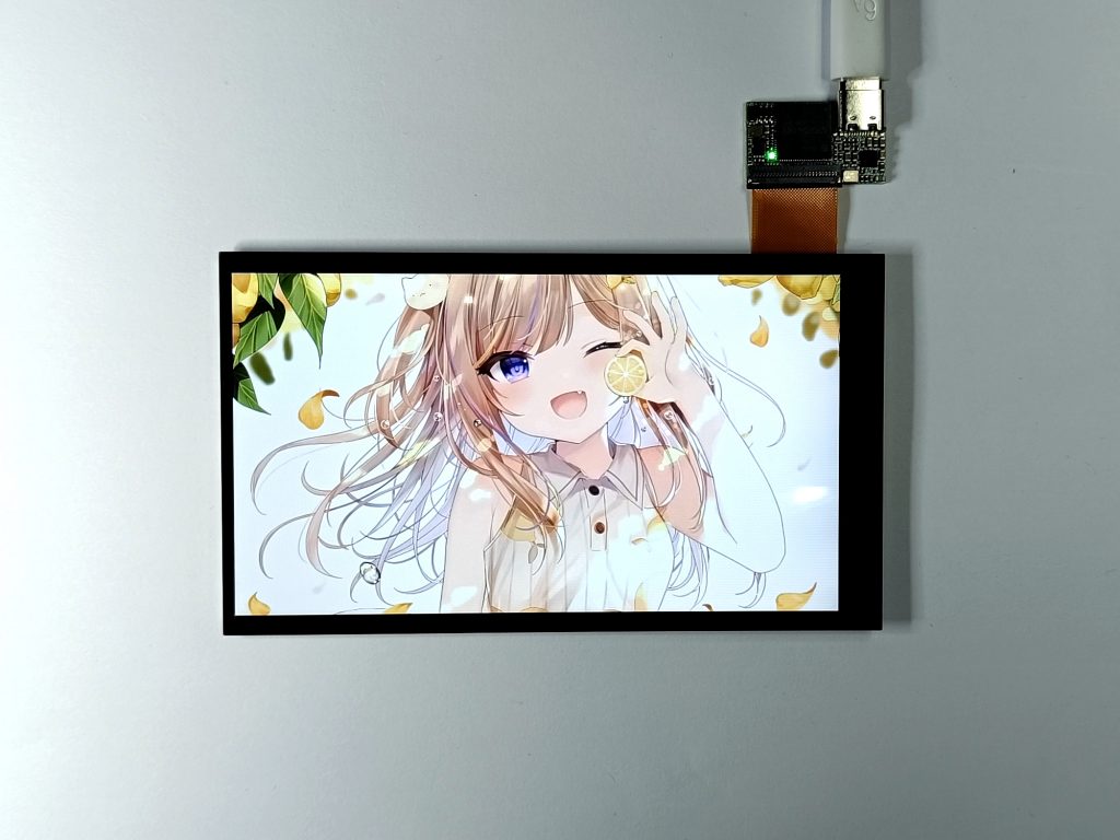
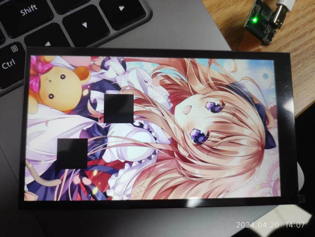
Screen: Special Command

The screen has some special commands which can be used to control its brightness and flip the screen, but because the command is not compatible for all type of screen, so test it before use it. Here is a reference for use such command.

For fbusb driver, we have a file named command in /sys folder, we can use it to send the command.

# turn off backlight
echo -e '\x00\x51\x02\x00\x00\x00\x00\x00' > `find /sys/devices/platform/ -name command`
# set backlight brightness to max
echo -e '\x00\x51\x02\x00\x00\x00\xff\x00' > `find /sys/devices/platform/ -name command`
# set backlight brightness to 128(half)
echo -e '\x00\x51\x02\x00\x00\x00\x80\x00' > `find /sys/devices/platform/ -name command`

Here is an example of libusb.

#include <stdio.h>
#include <stdlib.h>
#include <memory.h>

#include <libusb-1.0/libusb.h>

static libusb_context *context = NULL;
static libusb_device_handle *handle = NULL;

unsigned char cmd_rotate[] = {0x00, 0x36, 0x02, 0x00, 0x00, 0x00, 0x00, 0x00};
unsigned char cmd_backlight[] = {0x00, 0x51, 0x02, 0x00, 0x00, 0x00, 0x00, 0x00};

int main(int argc, char *argv[])
{   
    if (argc != 3) {
        printf("usage: send_cmd [cmd: m|b] [param]\n");
        printf("example: mirror by axis x,y [0,1,2,3]\n\tsend_cmd m 1\n");
        printf("example: set backlight [0~255]\n\tsend_cmd b 120\n");
        return 0;
    }
    
    libusb_init(&context);
    handle = libusb_open_device_with_vid_pid(context, 0xc872, 0x1004);
    if (handle == NULL) {
        printf("no device.\n");
        return -1;
    }

    libusb_claim_interface(handle, 0);
    libusb_set_interface_alt_setting(handle, 0, 0);
    
    switch (argv[1][0]) {
    case 'm':
        cmd_rotate[6] = atoi(argv[2]);
        libusb_control_transfer(handle, 0x40, 0xb0, 0, 0, cmd_rotate, 8, 100);
        break;
        
    case 'b':
        cmd_backlight[6] = atoi(argv[2]);
        libusb_control_transfer(handle, 0x40, 0xb0, 0, 0, cmd_backlight, 8, 100);
        break;
        
    default:
        printf("command is not supported.");
        break;
    }
        
    libusb_release_interface(handle, 0);
    libusb_close(handle);
    libusb_exit(context);
    return 0;
}

Also please check https://vocore.io/screen.html, the v2scrctl source code for libusb.

Screen: I2C to Drive RGB LEDs

Currently our V7B board has I2C interface exported, and actually we can control it through USB port.

Note: This I2C mainly is used for upgrade firmware on the usb bus, so it might be risk to use, if you send wrong data to it, it might broken firmware.

Here is the I2C API, only three commands:

#define CMD_SCREEN_I2C          0xb5
#define CMD_SCREEN_I2C_WR 0xb6
#define CMD_SCREEN_I2C_RD 0xb7

0xb5 is used to tell i2c bus how many data we will write and how many data we will read. 0xb6 and 0xb7 is used to read/write the data from/to device i2c buffer. max one time can send 58 – 5 = 53bytes, so for data better not to exceed 53 bytes.

Here is the example of writing data to I2C EEPROM, BLOCK_SIZE = 16.

        if (load_from_file(argv[2], buf, 0x2000) < 0) {
            printf("no firmware file.\n");
            return -1;
        }
        
        for (pos = 0; pos < 0x2000; pos += BLOCK_SIZE) {
            cmd[0] = EEPROM_ADDR;    // I2C address
            cmd[1] = BLOCK_SIZE + 2; // write 18 bytes for register address 2byte and data 16byte.
            cmd[2] = 0;              // read zero byte, no read for i2c write.
            cmd[3] = pos >> 8;       // write first byte, register address 
            cmd[4] = pos;            // write second byte, register address
            // put rest data to the buffer.
            memcpy(cmd + 5, buf + pos, BLOCK_SIZE);
            // send i2c command head to screen, require control the i2c bus.
            ret = libusb_control_transfer(handle, 0x40, CMD_SCREEN_I2C, 0, 0, cmd, BLOCK_SIZE + 5, 200);
            // write register address and data to i2c bus.
            ret = libusb_control_transfer(handle, 0xc0, CMD_SCREEN_I2C_WR, 0, 0, cmd, 1, 200);
            
            if (pos % 0x100 == 0) {
                printf(".");
                fflush(stdout);
            }
        }

Here is the example of reading data from I2C EEPROM

        for (pos = 0; pos < 0x2000; pos += BLOCK_SIZE) {
            cmd[0] = EEPROM_ADDR; // I2C address
            cmd[1] = 2;           // write two bytes for register address.
            cmd[2] = BLOCK_SIZE;  // read 16 bytes
            cmd[3] = pos >> 8;    // write data first byte
            cmd[4] = pos;         // write data second byte
            
            ret = libusb_control_transfer(handle, 0x40, CMD_SCREEN_I2C, 0, 0, cmd, 5, 200);
            // write register address to i2c bus.
            ret = libusb_control_transfer(handle, 0xc0, CMD_SCREEN_I2C_WR, 0, 0, cmd, 1, 200);
            // read data from i2c bus.
            ret = libusb_control_transfer(handle, 0xc0, CMD_SCREEN_I2C_RD, 0, 0, cmd, BLOCK_SIZE + 1, 200);
            
            memcpy(buf + pos, cmd + 1, BLOCK_SIZE);
            if (pos % 0x100 == 0) {
                printf(".");
                fflush(stdout);
            }
        }

With this I2C interface, we can easy control RGB LED driver chip like AW9523 and other chips. Then it will save a lot of cost make customized board, do not need arduino and USBhub chip anymore.

To be continue…

Screen: 7inch ready

After months hard work, the 7inch(6.8in exactly) screen is ready in time. 🙂

This screen is pretty special, because the screen main design target is for real car but not like our current 4inch/5inch screen for consumer usage. So it can stand even worse environment like hot area over 65C.

Here is its shape:

Screen: 5inch upgrade

New 5inch screen comes, old version will keep production for a while for compatible, but later we consider move to new version.

New screen(D500FPC9373-C) we have four improvements.

  1. stronger border, this is in order to provide better protection of the screen.
  2. increase backlight brightness.
  3. better color for display.
  4. better supply, old version screen driver chip is pretty shortage.

Also these improvements caused shape adjust. The display screen thickness increased 0.2mm, and border is wider 0.2mm. Touch screen and display area still same size.

PS: new screen currently only test with our screen_test and SimHub, rest application might not compatible, need to upgrade. For non-developer, recommend to keep using the old stable version to avoid any mystery problem.

Why shitty like PayPal still exists?!

This happens more than one time. I think we have already stand enough to use PayPal and need to find an alter one asap. It is too risk to use it for online shop.

Case is like this: some people go to our store and purchase something, suddenly they think they buy wrong items. And did not email us but open a disputes case and ask for refund. All in 5 minutes.

Once case is open, whatever we reply or we do not reply, it will be automaticlly submit and of course, buyer’s favor.

I really understand and willing to refund people for mistake buying from our store, but why the paypal charge us 8USD for dispute fee?! It is terrible.


I think move our store to aliexpress.com and use alipay is the only choice…

Screen: hand solder driver board to customized board

Some DIYers complained it is pretty hard for hand solder the small screen driver board on their designed board. So I find a way for them easier hand solder screen driver board to their board.

On the screen driver board bottom, we have some test points which is used for test at production also for SMT the board to other customized board. It is not designed for hand solder. We need some tricky for hand solder.

We can design like this, add a oval hole on the PCB, size should be enough for the thin iron

Then we can directly solder through the hole to the pads. This way we do not need use pins or other connectors, low cost and simple. 🙂

Attach the position of the pads(KiCAD), one note is they are on the bottom side.

For mass production, I still recommend directly use SMT machine solder it. :p

Code Tricky: why not optimize is_digit

Recently I need a super small bootloader for an arm chip, every bit need to be very careful used. When I read the code, I find an interesting function is_digit in printf.c, this blog will show common code and old expert code difference.

This function is used to check if a char is in the range of ‘0’ ~’9′, ascii is 48~57.

The common code is like this:

bool _is_digit_a(char ch)
{
    return (ch >= '0') && (ch <= '9');
}

This way is easy to read, but normally old fashion will write in another way, like this

bool _is_digit_b(char ch)
{
    return ((unsigned char)(ch - '0') <= 9);
}

Haha, actually they are same function, but second way looks like much smaller and faster.

Let’s do a simple test by gcc and its toolchain, first for x86 system:

call gcc -c test.c -o test.x86.o, then objdump -DSx test.x86.o, we can get machine code

0000000000000000 <_is_digit_a>:
0: f3 0f 1e fa endbr64
4: 55 push %rbp
5: 48 89 e5 mov %rsp,%rbp
8: 89 f8 mov %edi,%eax
a: 88 45 fc mov %al,-0x4(%rbp)
d: 80 7d fc 2f cmpb $0x2f,-0x4(%rbp)
11: 7e 0d jle 20 <_is_digit_a+0x20>
13: 80 7d fc 39 cmpb $0x39,-0x4(%rbp)
17: 7f 07 jg 20 <_is_digit_a+0x20>
19: b8 01 00 00 00 mov $0x1,%eax
1e: eb 05 jmp 25 <_is_digit_a+0x25>
20: b8 00 00 00 00 mov $0x0,%eax
25: 83 e0 01 and $0x1,%eax
28: 5d pop %rbp
29: c3 retq
000000000000002a <_is_digit_b>:
2a: f3 0f 1e fa endbr64
2e: 55 push %rbp
2f: 48 89 e5 mov %rsp,%rbp
32: 89 f8 mov %edi,%eax
34: 88 45 fc mov %al,-0x4(%rbp)
37: 0f b6 45 fc movzbl -0x4(%rbp),%eax
3b: 83 e8 30 sub $0x30,%eax
3e: 3c 09 cmp $0x9,%al
40: 0f 96 c0 setbe %al
43: 5d pop %rbp
44: c3 retq

so A takes around 15 commands and 42 bytes, and B takes 11 commands and 27 bytes, save approx 30%.

Then check arm, call arm-none-eabi-gcc -c test.c -o test.arm.o, then arm-none-eabi-objdump -Dsx test.arm.o

00000000 <_is_digit_a>:
0: e52db004 push {fp} ; (str fp, [sp, #-4]!)
4: e28db000 add fp, sp, #0
8: e24dd00c sub sp, sp, #12
c: e1a03000 mov r3, r0
10: e54b3005 strb r3, [fp, #-5]
14: e55b3005 ldrb r3, [fp, #-5]
18: e353002f cmp r3, #47 ; 0x2f
1c: 9a000004 bls 34 <_is_digit_a+0x34>
20: e55b3005 ldrb r3, [fp, #-5]
24: e3530039 cmp r3, #57 ; 0x39
28: 8a000001 bhi 34 <_is_digit_a+0x34>
2c: e3a03001 mov r3, #1
30: ea000000 b 38 <_is_digit_a+0x38>
34: e3a03000 mov r3, #0
38: e2033001 and r3, r3, #1
3c: e20330ff and r3, r3, #255 ; 0xff
40: e1a00003 mov r0, r3
44: e28bd000 add sp, fp, #0
48: e49db004 pop {fp} ; (ldr fp, [sp], #4)
4c: e12fff1e bx lr
4c: R_ARM_V4BX ABS
00000050 <_is_digit_b>:
50: e52db004 push {fp} ; (str fp, [sp, #-4]!)
54: e28db000 add fp, sp, #0
58: e24dd00c sub sp, sp, #12
5c: e1a03000 mov r3, r0
60: e54b3005 strb r3, [fp, #-5]
64: e55b3005 ldrb r3, [fp, #-5]
68: e2433030 sub r3, r3, #48 ; 0x30
6c: e20330ff and r3, r3, #255 ; 0xff
70: e3530009 cmp r3, #9
74: 93a03001 movls r3, #1
78: 83a03000 movhi r3, #0
7c: e20330ff and r3, r3, #255 ; 0xff
80: e1a00003 mov r0, r3
84: e28bd000 add sp, fp, #0
88: e49db004 pop {fp} ; (ldr fp, [sp], #4)
8c: e12fff1e bx lr
8c: R_ARM_V4BX ABS

A uses 20 instructions and B uses 16 instructions, saves 20%. Also no branch, more friendly to CPU workflow.

Final, try riscv, call riscv-none-embed-gcc -c test.c -o test.riscv.o, then riscv-none-embed-objdump -Dsx test.riscv.o

00000000 <_is_digit_a>:
0: 1101 addi sp,sp,-32
2: ce22 sw s0,28(sp)
4: 1000 addi s0,sp,32
6: 87aa mv a5,a0
8: fef407a3 sb a5,-17(s0)
c: fef44703 lbu a4,-17(s0)
10: 02f00793 li a5,47
14: 00e7fa63 bgeu a5,a4,28 <.L2>
14: R_RISCV_BRANCH .L2
18: fef44703 lbu a4,-17(s0)
1c: 03900793 li a5,57
20: 00e7e463 bltu a5,a4,28 <.L2>
20: R_RISCV_BRANCH .L2
24: 4785 li a5,1
26: a011 j 2a <.L3>
26: R_RISCV_RVC_JUMP .L3
00000028 <.L2>:
28: 4781 li a5,0
0000002a <.L3>:
2a: 8b85 andi a5,a5,1
2c: 0ff7f793 andi a5,a5,255
30: 853e mv a0,a5
32: 4472 lw s0,28(sp)
34: 6105 addi sp,sp,32
36: 8082 ret
00000038 <_is_digit_b>:
38: 1101 addi sp,sp,-32
3a: ce22 sw s0,28(sp)
3c: 1000 addi s0,sp,32
3e: 87aa mv a5,a0
40: fef407a3 sb a5,-17(s0)
44: fef44783 lbu a5,-17(s0)
48: fd078793 addi a5,a5,-48
4c: 0ff7f793 andi a5,a5,255
50: 00a7b793 sltiu a5,a5,10
54: 0ff7f793 andi a5,a5,255
58: 853e mv a0,a5
5a: 4472 lw s0,28(sp)
5c: 6105 addi sp,sp,32
5e: 8082 ret

A takes 54bytes and 20 instructions; B takes 38bytes and 14 instructions, save 30%. Also no branch, more friendly to CPU workflow.

test source code like this:

#include <stdbool.h>
#include <stdio.h>

bool _is_digit_a(char ch)
{
    return (ch >= '0') && (ch <= '9');
}

bool _is_digit_b(char ch)
{
    return ((unsigned char)(ch - '0') <= 9);
}

void main(void)
{
    for (unsigned char i = 0; i < 255; i++) {
        printf("%d is%s digit\r\n", i, _is_digit_a((char)i) ? "" : " not");
        printf("%d is%s digit\r\n", i, _is_digit_b((char)i) ? "" : " not");
    }
}

PS: actually for modern compiler, any optimize will make both same code, only 1/3 of not optimized size. 🙂 nothing really need to improve now. Way A is the better way for it is more readable.

So final note, do not forget -O when you use gcc :p

VoCore2: OpenWrt 21.02 Patch/Compile-2

This blog focus on microSD support.

Because I already know it is cd-polling problem, so directly go to source code, see if the polling is supported in this version.

Source code position is at openwrt-21.02.1/target/linux/ramips/files/drivers/mmc/host/mtk-mmc/sd.c

... line 2249 ...
if (of_property_read_bool(pdev->dev.of_node, "mediatek,cd-poll"))
    mmc->caps |= MMC_CAP_NEEDS_POLL;

... line 442 ...
if (host->mmc->caps & MMC_CAP_NEEDS_POLL)
    inserted = 1;

... line 1862 ...
if (host->mmc->caps & MMC_CAP_NEEDS_POLL)
    present = 1;

Looks like my patch is already combined to 21.02, so once I add this mediatek,cd-poll to VoCore2 Ultimate DTS it will just works.

We can directly modify openwrt-21.02.1/target/linux/ramips/dts/mt7628an_vocore_vocore2.dts to make VoCore2 support SD card. For simple, attach four lines to end of the dts file.

&sdhci {
	status = "okay";
	mediatek,cd-poll;
};

Now, after this patch, make sure kmod-mmc, kmod-sdhci-mt7620 is selected in kernel.

Compile OpenWrt, then upload to VoCore2, it just works.

PS: if your VoCore do not have SD card slot, enable sdhci polling mode will cause it output error log every two seconds. So this driver is not default enable in VoCore2 device tree.

VoCore2: OpenWrt 21.02 Patch/Compile-1

OpenWrt 21.02.2 is pretty stable, the even better part is it supports WPA3. Official OpenWrt 21.02.2 release directly work with VoCore2 SBC version, but for VoCore2 Ultimate version, we have some external devices need to be supported, so this blog and following blogs I will write down the process I patch OpenWrt 21.02.

There are three main parts:

  1. microSD card can not detect or read.
  2. ES8388 sound card can not work.
  3. DTS(device tree) need to update add 1,2 setting.

In my experience, microSD problem is mainly caused by default mmc driver who do not support cd-polling. cd-polling is used to scan the microSD card insert into the slot but not using card detect pin. Actually I have already submit this patch to 18.06 and 19.07, so I just need to copy and paste the patch to make it work on 21.02.

ES8388 sound card driver code is already in Linux system. For 19.07 I have a dirty patch. The better way is to write a simple clock control driver, and use DTS to setup it. For this version, I will try to make it.

DTS, this is pretty painful to learn because current tutorial is not very friendly for beginner. I will try to write another not that painful tutorial…

Screen: WinUSB Install + New Test App

I find libusbk sometimes crash the system, so maybe winusb is a good choice. Before you install WinUSB, remember to install libusbK first.

Here is a simple tutorial about install winusb driver.

First download zadig, it is include in https://vocore.io/misc/v2scrctl-release.zip, in folder v2scrtest.

Plug in the screen and run zadig.exe

Select USB2.0 Screen from the list. Then click Install Driver. (If already installed, it will be Reinstall Driver, normally do not need install again).

Install will take around 2 minutes.

After that, for win10 or upper system can directly run v2scrctl.exe for test the screen.

You can drag and drop test.jpg or any other picture file to the window to let it show on the screen. Also it can show the touch points from the screen.

Have fun!

.