From last year Sep.1, we meet global chip shortage. Recently some chips price increase to incredible level. My chip provider told me, currently STM32F103 price is around 72CNY/pcs(11USD/pcs) compare to early of last year only 3~5CNY. Another network chip IP101G, from 0.8~1CNY to 10CNY. 🙁 This is really crazy.
PS: Lucky, I use Gigadevice MCU, pin to pin STM32 but need to recompile firmware. Its price increased 10%~15%, compare to STM32 chip, looks like it is reasonable and acceptable.
For our production VoCore2 and camera, we have enough stock, but screen driver chip now have problem. The chip factory give me 25~30 weeks lead time, that is over half year. We have to change current screen plan.
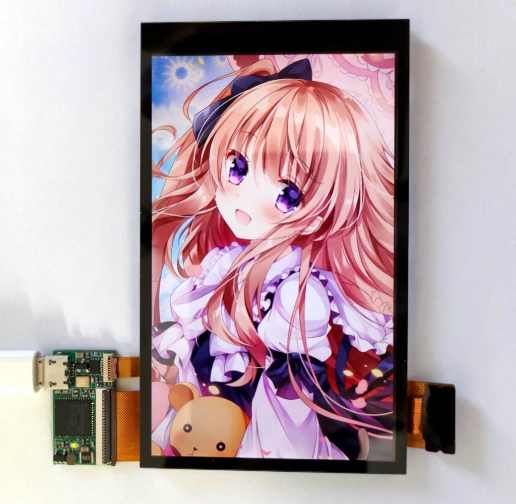
New screen is from Toshiba, better color than our old one. In order to compatible with old design, we add a FPC to convert its connector. For order later than Feb.9, we will all ship this screen. In software level they are compatible.
One slight difference, old screen once power on will show a white screen, this new one show black screen as default.
Screen size is almost same as old version(around 0.5mm smaller for both sides) also FPC is bendable, so this design should be compatible to most old screen enclosure.
Finally, here is its photo: