
Now VoCore is on indiegogo 🙂 The people who want to buy it have a better way. Please support this campaign, or it will become my personal toy. 😀
Link is here: VoCore Indiegogo.com Campaign Link
Now VoCore is on indiegogo 🙂 The people who want to buy it have a better way. Please support this campaign, or it will become my personal toy. 😀
Link is here: VoCore Indiegogo.com Campaign Link
It works. Someone said it is hard and have to change RT5350 wifi driver code, but I did not change any code, maybe the developers of openwrt already fix that? 🙂
SSID for AP mode is VoCore
SSID for STA mode(my house router) is VongerWifi
That is not hard to setup:
First, enable STA mode, add two lines to the end of /etc/config/network.
config interface wwan
	option proto 'dhcp'
Then change /etc/config/wireless
config wifi-device  radio0
	option type     mac80211
	option channel  11
	option hwmode	11ng
	option path	'10180000.wmac'
	list ht_capab	GF
	list ht_capab	SHORT-GI-20
	list ht_capab	SHORT-GI-40
	list ht_capab	RX-STBC1
	option htmode	HT20

config wifi-iface
	option device   radio0
	option network  lan
	option mode     ap
	option ssid     VoCore
	option encryption none

config wifi-iface
	option device   radio0
	option network  wwan
	option mode     sta
	option ssid     VongerWifi
	option encryption psk2
	option key      PasswordForWifi
If your house router has taken 192.168.1.1 as its IP address, you have to change the setting in /etc/config/network, set openwrt ip to other, so it will not conflict with your house router in STA mode. The ip in example is 192.168.61.1.
config interface 'lan'
	option ifname 'eth0.1'
	option type 'bridge'
	option proto 'static'
	option ipaddr '192.168.61.1'
	option netmask '255.255.255.0'
	option ip6assign '60'
After that, looks everything works fine. My computer is able to connect to VoCore and VoCore is able to connect to internet through my wifi. But the only problem is my computer can not connect to internet through VoCore, maybe I have to setup a route on the board, will study on that later.
I opened a facebook page today, have fun!
https://www.facebook.com/VoCore
Do not hesitate to press LIKE!
PS: It is so hard to login to facebook from China, XD.
About 10 meters from my home router(half is walled)
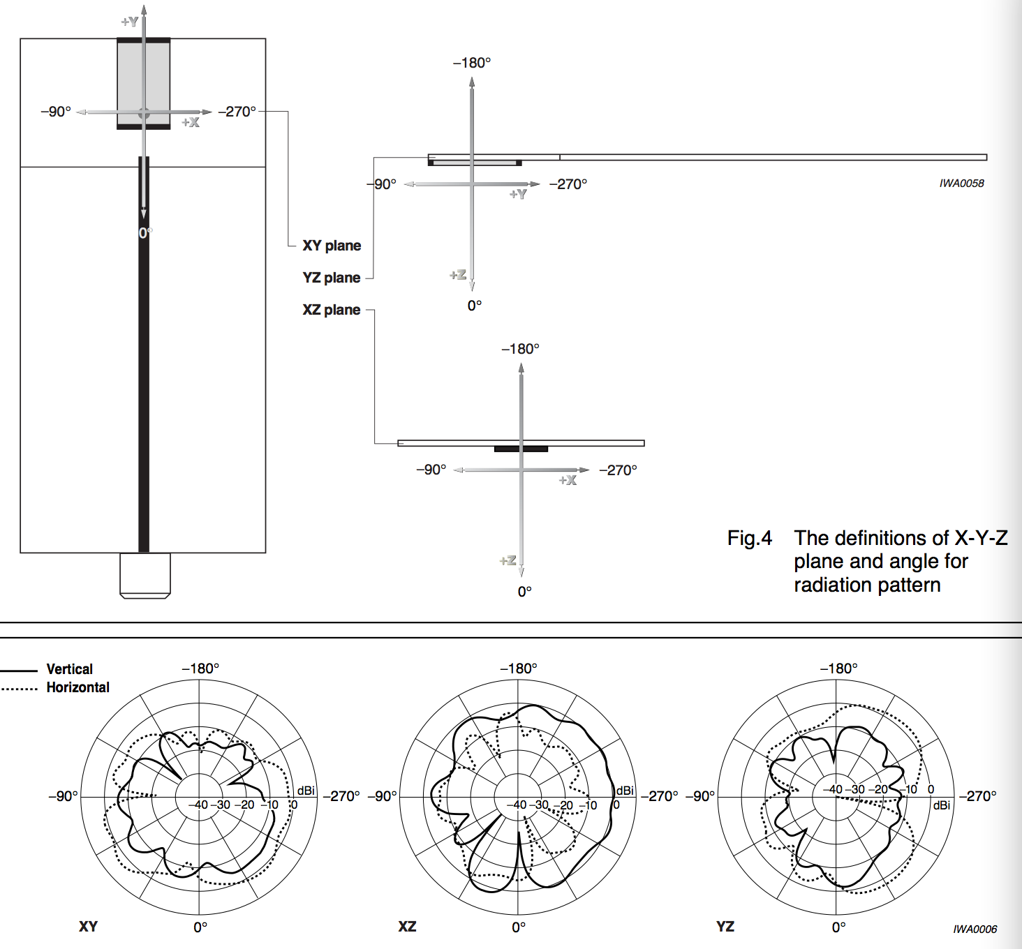
X-Y, Y-Z, X-Z direction for 10 times test, average value:
YAGEO:CAN4311153002451K(4dbi), 5.3 x 2.0 -> -70dBm
Supermax: IAN0201(2dbi), 5.2 x 2.0 -> -72dBm
Sunlord: SLDA72-2R470G-S1(2.5dbi) 5.0 x 2.0 -> -68dBm
Rainsun: AN3216-245 3.2×1.6(0.5dbi) -> -72dBm
????: PCB IPX antenna -> -80dBm
So, after that test, remove the IPX for more clearance zone is a better choice.
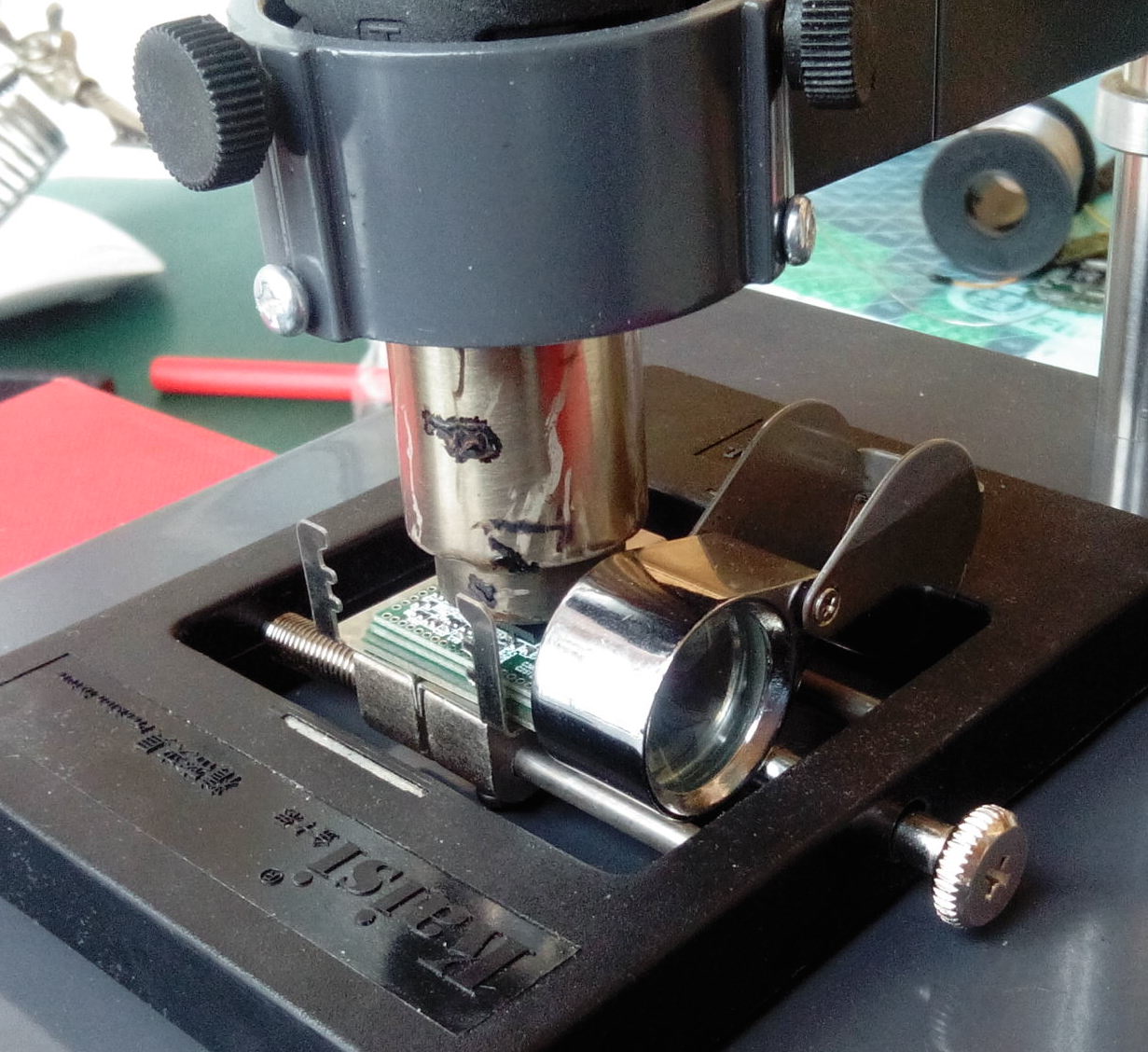
IT IS SO HARD!!!
I have made 8 VoCore v0.5 but only 2 works, Rest are all NG at BGA part…
The problem is my paste is Sn-Bi-Ag(176℃), but BGA balls are Sn-Ag-Cu(226℃), I make the hot air to 320℃ the balls are melted down but can not touch and connect to PCB pads.
After serval test, I find a way. Paste under BGA is necessary, put paste on PCB BGA part first, then put RT5350 on that, MUST perfectly on its top. Then use hot air 220℃ until paste is melted about 30 seconds. Rise to 280℃ about 30 seconds, balls and paste will combine to one. After cool down, everything is just fine.
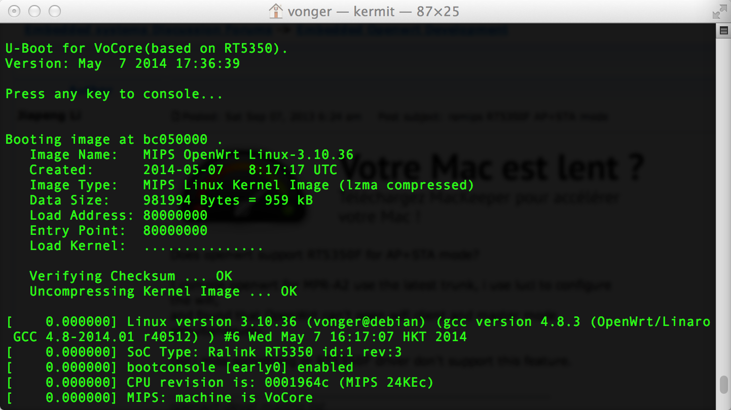
Changed from official U-Boot 1.1.3 for RT5350, remove useless information from the official version. Changed wait time from 5 second to 1 second, now VoCore boots a little faster and the console is more clear. 🙂
I should get my new v0.5 PCB board today, but because of the holiday of May.1, I have to wait three days more. I am patient 🙂
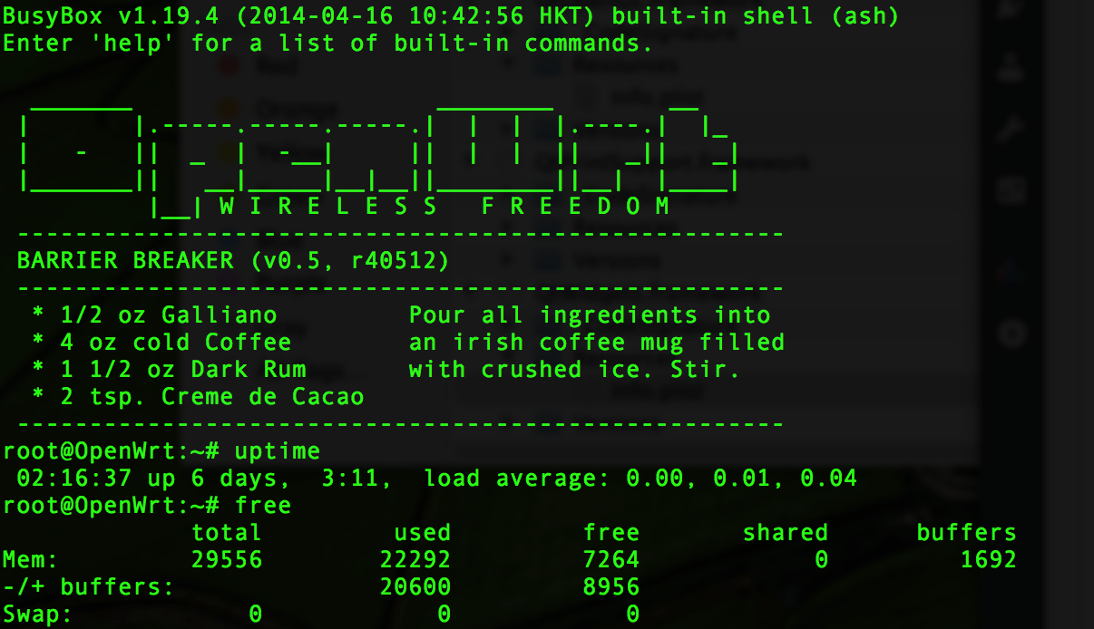
The software part should be stable, has run almost 10 days without a mistake. Unfortunately, the road of Taiyuan is under repairing…my power is cut off this morning, so I can not capture new picture for uptime or continue my stable test.
For the hardware part, I will do three tests.
1. replace 1.2nF to 0.1uF.
90% routers and even raspberrypi are using 0.1uF for the ethernet circuit part, but all MTK/Ralink routers are using 1.2nF or 1nF. Why? That is for ethernet signal, so I think it do not have relation with RT5350 chip. I will test and compare, then the truth will soon be revealed to the world 🙂
RT5350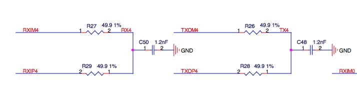
AR9331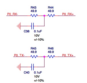
RaspberryPi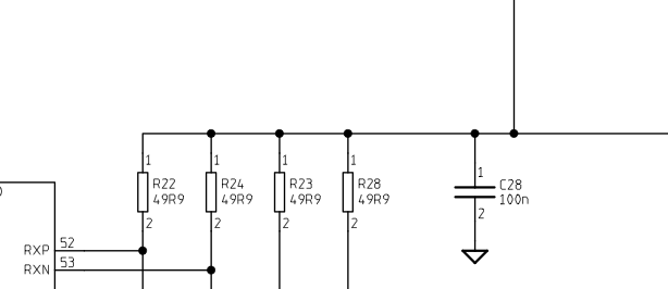
2. on board ceramic antenna.
I have tried my best to leave 5.5mm clearance zone for that ceramic antenna, if its performance is too low(<60% 4dBi IPX antenna), I will remove it. Maybe more clearance zone will be better but need to test.
from CAN4311153002451K manual:
3. 22nF to 0.1uF, 4.7uF to 1uF, 1.5pF to 1.2pF
on my board, C8,B5,A5,B3,C9 connected to 22nF, that should be used to make wifi part 1.2V stable, so change it to 0.1uF should be better, but might effect signal, need to test.
on my board I have seven 4.7uF, I do not think that is necessary. This board size is very small, and already have two super big 22uF to stable its power on 3.3V. Replace 4.7uF to 1uF should be acceptable.
on antenna part, 1.5pF(+/-0.25pF) is almost same as 1.2pF(+/-0.25pF), so why use one more capacitance type?
AR2317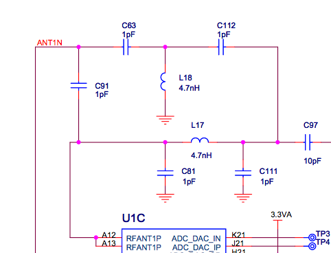
MT7620A
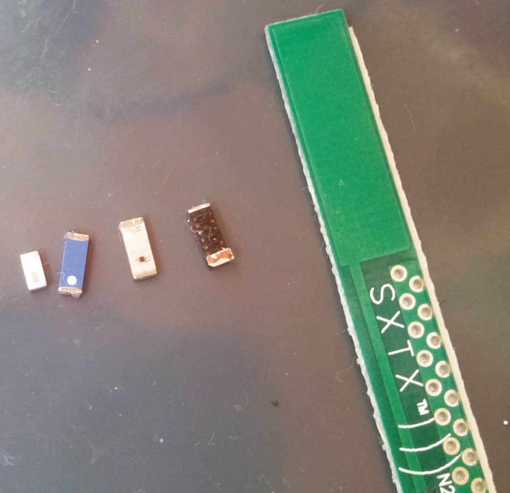
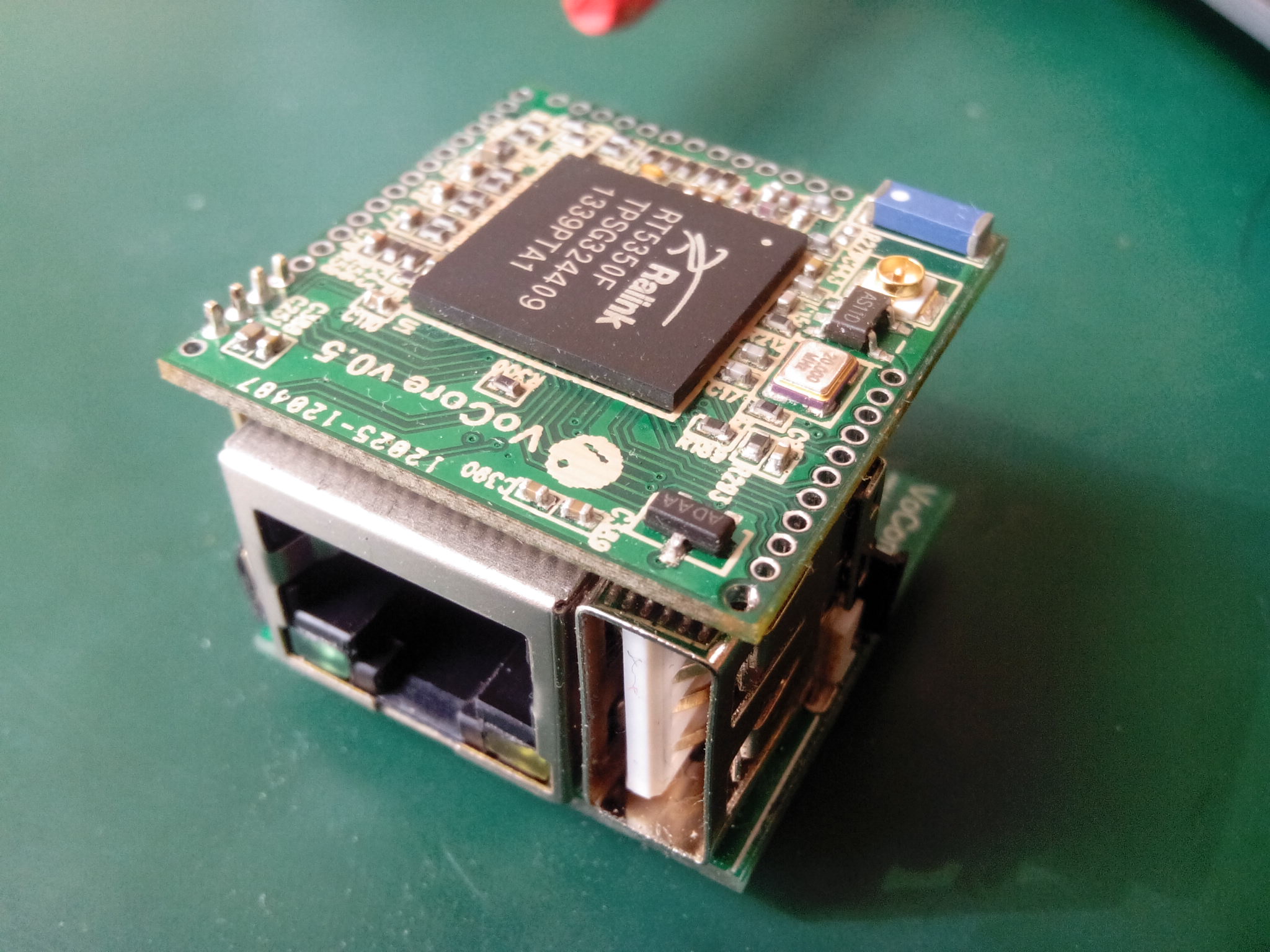
VoCore v0.3 is not that easy to test, so I make a dock for v0.5.
Its size is 2.5×2.5×1.6. Once connect it to VoCore v0.5, the total size of the two will be 2.5×2.5×2.0.
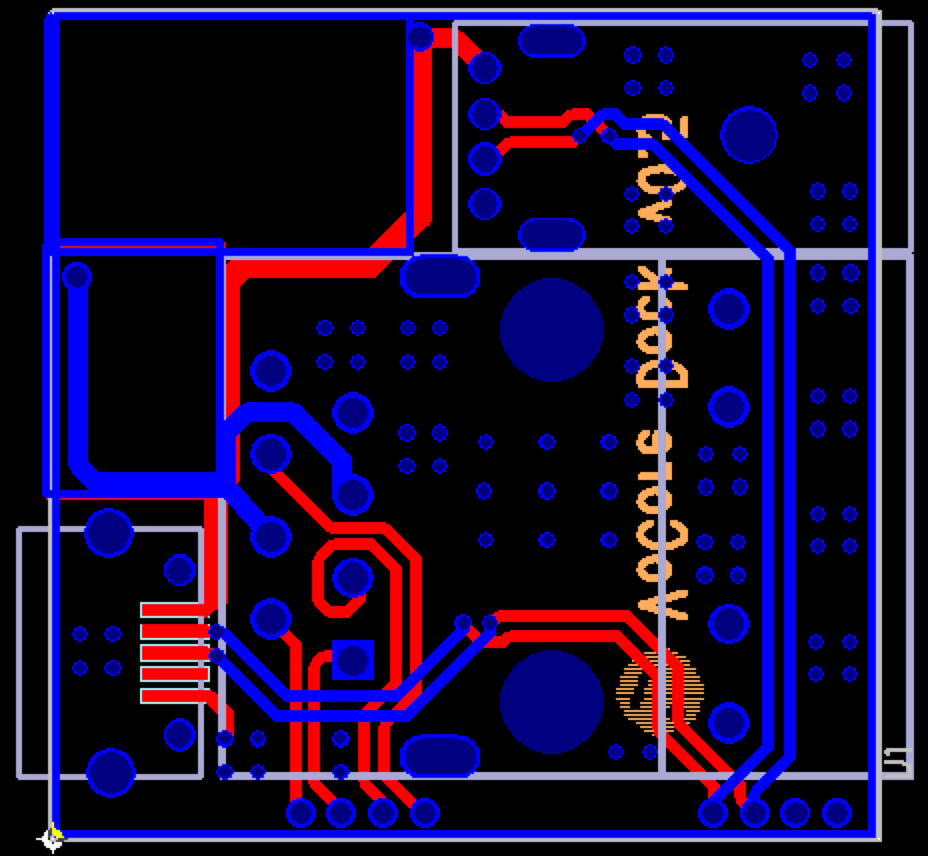
This dock contains three parts.
A: USB1(left bottom) is used for power +5.0V, it should be connected to USB power.
B: USB2(top right) is a full function USB.
C: RJ45(right bottom) is for WLAN/LAN connection, connected to EPHY_P0.
It is not the final version of the dock.
From Apr.23, I kept one of my board running. 🙂
![]()