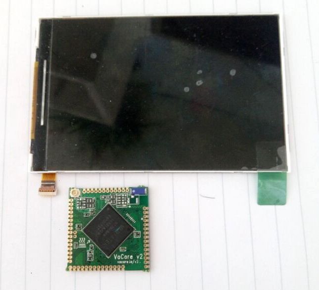
Last week I find a SPI screen(480×320+262K Color) in the dust, guess it’s time to make it work 🙂
First of all, read read and read.


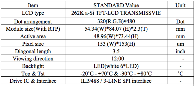
Actually I can not find much useful information from the lcd datasheet. The two tables should be enough.
LCD have three parts: a driver chip, which is ILI9488; a TFT display, mine is 480×320; backlight, normally is several white LEDs, mine LCD has six of them.
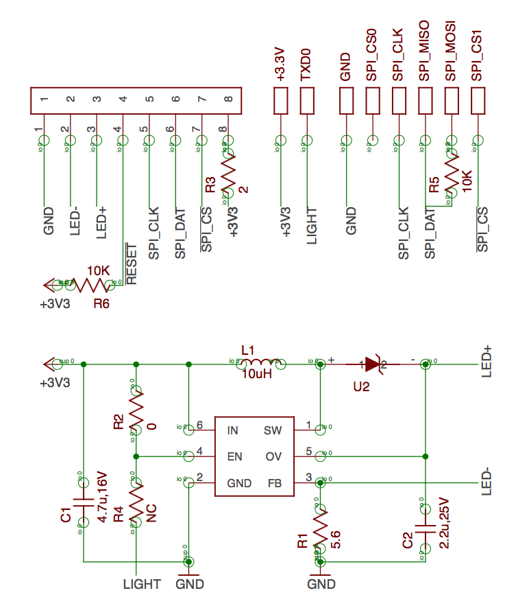
LED- & LED+ the two pins are used to drive white LEDs, drive one LED voltage is 2.5V~3V, six of them in serial will take 15~18V, we will need a boost dcdc chip to reach that voltage, convert 3.3V input to 18V, for simple, just copy and paste the typical sch of the dcdc to my sch).
VCI(2.8V) is the input power for LCD, max allowed voltage is 3.3V, but better to use a small resistor to lower the input voltage to avoid power peak damage the drive chip.
NCS/SDA/SCL is the standard 3-wires SPI interface, we should rename them to SPI CS, SPI DAT, SPI CLK. SPI DAT is for data input and output.
Here is a tricky part, VoCore2 is using 4-wires SPI, which requires four pins: SPI CS, SPI MOSI, SPI MISO, SPI CLK. We must combine SPI MOSI, SPI MISO to SPI DAT, but MISO & MOSI will crosstalk to each other. To lower the crosstalk, we can use a resistor between them.
LCD screen power consume is around 400mW ==> 18V(20mA), and VoCore2 3.3V power output is 200mA~300mA(3.3V 600mW), should be enough.
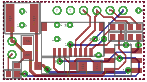
PCB Layout, two layers, super small, only 0.75×1.34cm, put at top left of vocore2 border 🙂
PS: now the PCB is making in factory, I will get them next week.
You see? Develop hardware is not that hard. 🙂

