New forum is ready: forum.vocore.io
Now I am trying to move the old vonger.cn/?forum=vocore threads to the new forum. 🙂
This should be the final forum shape.

New forum is ready: forum.vocore.io
Now I am trying to move the old vonger.cn/?forum=vocore threads to the new forum. 🙂
This should be the final forum shape.
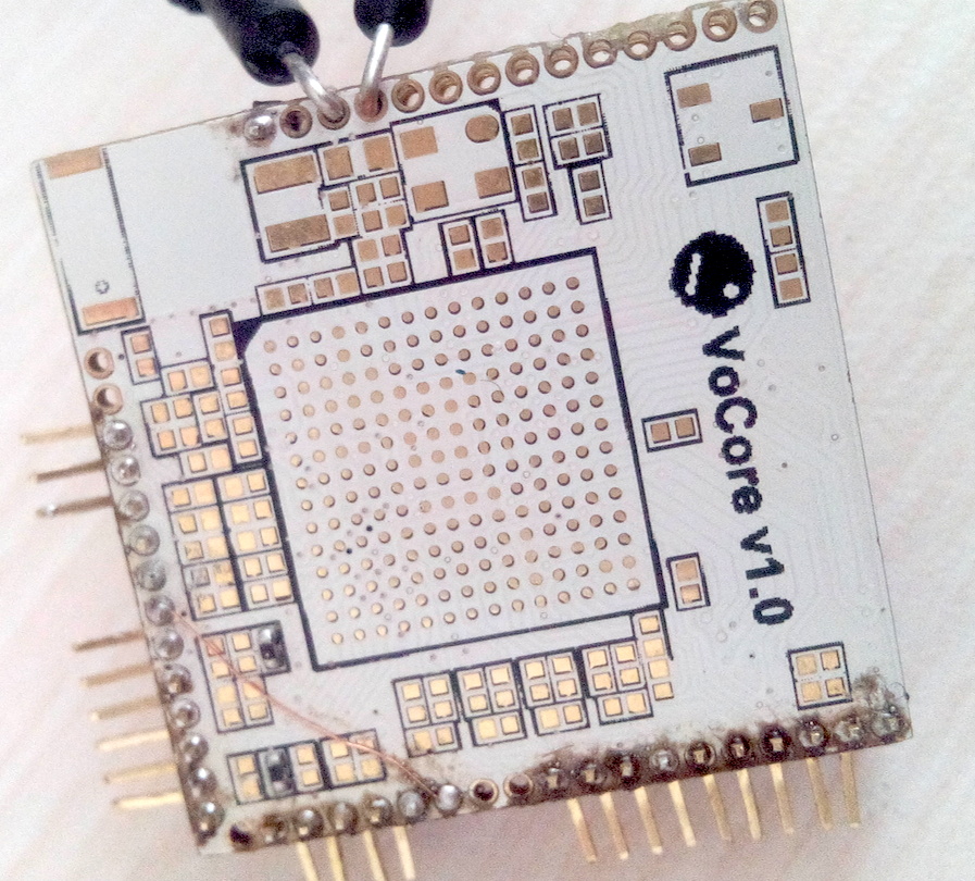
The VoCore without dock shipped today 🙂

I am crazy…
The factory just made a new big mistake(or accident), they deleted all the test log, just for a stupid reason, those test logs took too much disk space…and they ‘think’ the productions had done the test, that should be useless. Simply ignore my notify, ye, I notified them to keep the log at least three times, in face or phone call. T-T Now they are trying to recover the deleted data…
I planed to use that log to trace the production quality…If user gets the VoCore but has problem, at least I have some data to trace.
They agree if the log can not back, they will test again, but I can not wait. Just hope the log be recovered.
Enable two UARTs for VoCore, one UART lite, one UART full.
Just need to change DTS a little:(VOCORE.dts under openwrt source code)
First, enable uart@500
uart@500 {
    status = "okay";
};
Then, remove uartf from ralink,group:gpio.
pinctrl {
    state_default: pinctrl0 {
        gpio {
            ralink,group = "jtag", "led"; -> remove "uartf"
            ralink,function = "gpio";
        };
    };
};
Finally, delete the code that export uartf as gpio:
in gpio-export section, remove gpio7, gpio8, gpio9, gpio10, gpio11, gpio12, gpio13, gpio14. If we keep them will get some error in log, but no effect to system boot.
PS: find a possible bug here, gpio10 and gpio11 are missed 🙂
Now good news is the two UARTs work same time, bad news is we lose eight gpio. 😉
Hope one day a hero will make a new rt5350-uart driver, so that allows ralink-function=”uartf,gpio”, then we can save 4 gpios. It is a good chance to practise Linux driver code. 😀
The new site has opened recently 🙂
I try to make the site as simple as possible, hope you like it.
Special thanks to Kovács Kornél, a great work.
Some parts are still under construction, if you have good idea, please mail to vonger@live.com.
Especially the wiki part 😀

Just waiting for factory…So I am on SPI again. 🙂
Last time I have done the driver, but it is not working with mmc. I think there must be something wrong with it, but after my test, the driver works quite well, so I guess I should make some mistake in mmc driver config.
NEW SOURCE CODE HERE: spi-rt2880.c
I soldered another flash to a bare VoCore board, so I do not have to solder the eight wires. Connect CS1->CS0, SPICLK->SPICLK, MOSI->MOSI, MISO->MISO, also pull HOLD/WP to high, so now VoCore SPI1 is controlling the second flash.
It works very well by current openwrt in high speed(>935KHz).
Add the following code to replace spidev@1 in VOCORE.dts, set the flash to 500KHz.
m25p80@1 {
    #address-cells = <1>;
    #size-cells = <1>;
    compatible = "w25q128";
    reg = <1>;
    linux,modalias = "m25p80", "w25q128";
    spi-max-frequency = <500000>;

    partition@0 {
        label = "xxxx";
        reg = <0x0 0x1000000>;
    };
};
Hardware part connection:
From my test, the data is normal.
root@OpenWrt:/sys/devices/10000000.palmbus/10000b00.spi/spi_master/spi32766/spi32766.1# ls
driver      factory_id  modalias    mtd         subsystem   uevent
root@OpenWrt:/sys/devices/10000000.palmbus/10000b00.spi/spi_master/spi32766/spi32766.1# cat factory_id
D26210-44DB40312F
Its log:
Mon Sep 29 02:06:27 2014 authpriv.notice dropbear[1175]: Password auth succeeded for 'root' from 192.168.61.159:58928
Mon Sep 29 02:07:19 2014 kern.warn kernel: [ 1461.940000] m25p80 spi32766.1: low speed mode.
Mon Sep 29 02:07:19 2014 kern.warn kernel: [ 1461.960000] m25p80 spi32766.1: delay = 1000
Mon Sep 29 02:07:19 2014 kern.warn kernel: [ 1461.970000] m25p80 spi32766.1: low speed mode.
Mon Sep 29 02:07:19 2014 kern.warn kernel: [ 1461.980000] m25p80 spi32766.1: delay = 1000
Mon Sep 29 02:07:19 2014 kern.warn kernel: [ 1461.980000] m25p80 spi32766.1: cs = 1, on
Mon Sep 29 02:07:19 2014 kern.warn kernel: [ 1462.000000] m25p80 spi32766.1: bit/x: 8,5
Mon Sep 29 02:07:19 2014 kern.warn kernel: [ 1462.000000] m25p80 spi32766.1: low speed mode.
Read data from the flash is also normal, just a little slow:
root@OpenWrt:/# hexdump -C /dev/mtdblock6 | head -10
00000000  27 05 19 56 d6 62 66 a6  53 88 7f 17 00 01 96 c0  |'..V.bf.S.......|
00000010  80 20 00 00 80 20 00 00  a3 c1 ed e5 05 05 01 00  |. ... ..........|
00000020  53 50 49 20 46 6c 61 73  68 20 49 6d 61 67 65 00  |SPI Flash Image.|
00000030  06 50 00 00 00 00 00 00  00 00 00 00 00 00 00 00  |.P..............|
00000040  ff 00 00 10 00 00 00 00  fd 00 00 10 00 00 00 00  |................|
00000050  e9 01 00 10 00 00 00 00  e7 01 00 10 00 00 00 00  |................|
00000060  e5 01 00 10 00 00 00 00  e3 01 00 10 00 00 00 00  |................|
00000070  e1 01 00 10 00 00 00 00  df 01 00 10 00 00 00 00  |................|
00000080  dd 01 00 10 00 00 00 00  db 01 00 10 00 00 00 00  |................|
00000090  d9 01 00 10 00 00 00 00  d7 01 00 10 00 00 00 00  |................|
I think last time I should did something wrong in the mmc driver config…
Many people ask me about how to pass the FCCID. In fact, the process is not that complex.
That is benefit to there are many module companies’ productions are using RT5350 in ShenZhen, and the foundry I choose has such production already(they also many good software, I am free to use). So I just send VoCore sample to the laboratory, and leave the foundry engineer’s phone number to the laboratory, they did rest for me, that saved me a lot of time.
PS: before the sample send to Lab, the beta version has already tested in factory, all results look good, so my confidence is from there.
About the sample, first of all, the board must in good quality. I am not sure what test they will do, but if the quality is not good, it might broken in half way. My samples are made by machine, better than my hand make ones.
About the test process, I knows little about that, I only know if the EMC can not pass, the laboratory will ask you if you want to add a metal shell, then do the test again(of course, your FCCID production photo will show the shell too, and your final production must have that metal shell)
VoCore passed FCCID in one time without any shell, that should thanks to the simulation software, when I design it, I set its simulation parameters to 1GHz, 3.3V to all traces, the sim result max crosstalk voltage is under 60mV, it should be a good result due to other board such as RM04 the crosstalk value greater than 300mV, its 30% traces even more than 800mV, maybe such reason they have to have a shell. The software I used name is HyperLync. 🙂
To lower the crosstalk voltage, we must keep trace distance 3W at least. And the trace should as short as possible.
Autumn comes, my house temperature is 25C, and test on new VoCore with dock several hours, the max temperature on the surface is lower than 50C, very good 🙂 not hot anymore, just a little warm.
Now, looks like everything is back to normal, all parts are ready now.
This is the ship time update:
If no big issue again, VoCore will be in SMT line about this Wednesday.
SMT will be done about this Sat, then test will take 3~4 work days.
Sep.30~Oct.6, the seven days is China National Day, so factory will not do any work.
Today will prepare the early bird ship.(early bird with dock will ship with the composed batch).
Oct.7 will ship the VoCore without dock.
VoCore + Dock(solder the pins, compose VoCore & Dock, package and test) will take about 5~7 work days.
So composed VoCore + Dock will ship about Oct.13~Oct.17.
From the factory, all docks are ready…
(The pictures are not the final one)

(Still need to solder pins)
(Still need some clean up)

Bad news and good news.
Bad news first: The factory get wrong chip type…I need W25Q64FVTIM(3.3V) but they get W25Q64??TIM(1.8V). The engineer find that when they count the chips…And even worse, all W25Q64FVTIM has sold out(I think winbond should thank to my ‘ advertisement’, due to last half year, nobody buy that chip) Next batch of chips have to wait at least four weeks. That means the ship time will be next month.
I hate Murphy’s theorem :'( There are a lot of people waiting, I can not hold…
Good news: There are some W25Q128FVTIM in store, at least enough for my first batch 🙂 All indiegogo VoCores will upgrade to that chip, means the flash is upgrade from 8MB to 16MB, free. And for Limited version without dock, will have a free DIY dock; Limited Version with dock will have a free shell(made by 3D printer).
Sorry for the delay, hope everyone have a happy day. 🙂