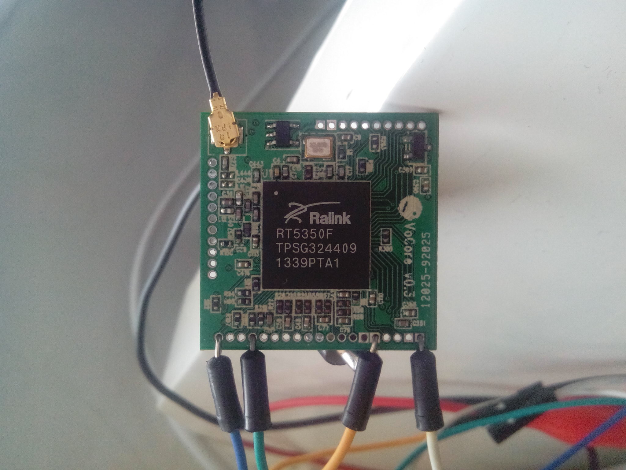
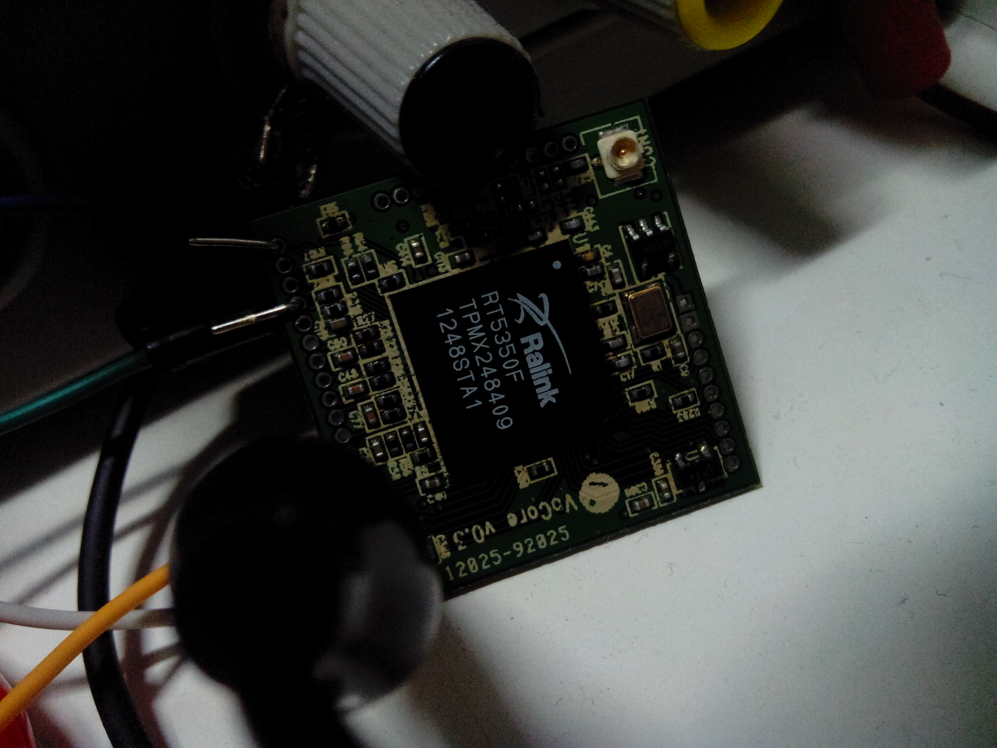
After get out that RT5350F from the board, I find the solder is normal. Every ball touched its pad, so this might not be solder problem.
I have to check software again. Get boot log from normal board and the bug board again, compare the two.
normal one:
U-Boot 1.1.3 (Nov 26 2013 - 19:17:30)
Board: Ralink APSoC DRAM: 32 MB
relocate_code Pointer at: 81fb4000
******************************
Software System Reset Occurred
******************************
spi_wait_nsec: 42
spi device id: ef 40 17 0 0 (40170000)
find flash: W25Q64BV
raspi_read: from:30000 len:1000
.*** Warning - bad CRC, using default environment
============================================
Ralink UBoot Version: 4.0.0.0
--------------------------------------------
ASIC 5350_MP (Port5<->None)
DRAM_CONF_FROM: Boot-Strapping
DRAM_TYPE: SDRAM
DRAM_SIZE: 256 Mbits
DRAM_WIDTH: 16 bits
DRAM_TOTAL_WIDTH: 16 bits
TOTAL_MEMORY_SIZE: 32 MBytes
Flash component: SPI Flash
Date:Nov 26 2013 Time:19:17:30
============================================
icache: sets:256, ways:4, linesz:32 ,total:32768
dcache: sets:128, ways:4, linesz:32 ,total:16384
##### The CPU freq = 360 MHZ ####
 estimate memory size =32 Mbytes
Please choose the operation:
 1: Load system code to SDRAM via TFTP.
 2: Load system code then write to Flash via TFTP.
 3: Boot system code via Flash (default).
 4: Entr boot command line interface.
 7: Load Boot Loader code then write to Flash via Serial.
 9: Load Boot Loader code then write to Flash via TFTP.
 4
You choosed 3
0

3: System Boot system code via Flash.
## Booting image at bc050000 ...
raspi_read: from:50000 len:40
. Image Name: MIPS OpenWrt Linux-3.10.32
 Created: 2014-03-20 13:56:37 UTC
 Image Type: MIPS Linux Kernel Image (lzma compressed)
 Data Size: 981825 Bytes = 958.8 kB
 Load Address: 80000000
 Entry Point: 80000000
raspi_read: from:50040 len:efb41
............... Verifying Checksum ... OK
 Uncompressing Kernel Image ... OK
No initrd
## Transferring control to Linux (at address 80000000) ...
## Giving linux memsize in MB, 32
Starting kernel ...
[ 0.000000] Linux version 3.10.32 (vonger@debian) (gcc version 4.8.3 (OpenWrt/Linaro GCC 4.8-2014.01 r39957) ) #3 Thu Mar 20 21:56:24 HKT 2014
[ 0.000000] SoC Type: Ralink RT5350 id:1 rev:3
[ 0.000000] bootconsole [early0] enabled
[ 0.000000] CPU revision is: 0001964c (MIPS 24KEc)
[ 0.000000] MIPS: machine is VoCore v0.3
[ 0.000000] Determined physical RAM map:
[ 0.000000] memory: 02000000 @ 00000000 (usable)
[ 0.000000] Initrd not found or empty - disabling initrd
[ 0.000000] Zone ranges:
[ 0.000000] Normal [mem 0x00000000-0x01ffffff]
[ 0.000000] Movable zone start for each node
[ 0.000000] Early memory node ranges
[ 0.000000] node 0: [mem 0x00000000-0x01ffffff]
[ 0.000000] Primary instruction cache 32kB, VIPT, 4-way, linesize 32 bytes.
[ 0.000000] Primary data cache 16kB, 4-way, VIPT, no aliases, linesize 32 bytes
[ 0.000000] Built 1 zonelists in Zone order, mobility grouping on. Total pages: 8128
[ 0.000000] Kernel command line: console=ttyS0,57600 rootfstype=squashfs,jffs2
[ 0.000000] PID hash table entries: 128 (order: -3, 512 bytes)
[ 0.000000] Dentry cache hash table entries: 4096 (order: 2, 16384 bytes)
[ 0.000000] Inode-cache hash table entries: 2048 (order: 1, 8192 bytes)
[ 0.000000] Writing ErrCtl register=0007a400
[ 0.000000] Readback ErrCtl register=0007a400
[ 0.000000] Memory: 29356k/32768k available (2132k kernel code, 3412k reserved, 544k data, 200k init, 0k highmem)
[ 0.000000] SLUB: HWalign=32, Order=0-3, MinObjects=0, CPUs=1, Nodes=1
[ 0.000000] NR_IRQS:256
[ 0.000000] CPU Clock: 360MHz
[ 0.000000] Calibrating delay loop... 239.61 BogoMIPS (lpj=1198080)
[ 0.070000] pid_max: default: 32768 minimum: 301
[ 0.070000] Mount-cache hash table entries: 512
[ 0.080000] pinctrl core: initialized pinctrl subsystem
[ 0.090000] NET: Registered protocol family 16
[ 0.130000] bio: create slab <bio-0> at 0
[ 0.140000] rt2880_gpio 10000600.gpio: registering 24 gpios
[ 0.150000] rt2880_gpio 10000600.gpio: registering 24 irq handlers
[ 0.160000] Switching to clocksource MIPS
[ 0.170000] NET: Registered protocol family 2
[ 0.180000] TCP established hash table entries: 512 (order: 0, 4096 bytes)
[ 0.200000] TCP bind hash table entries: 512 (order: -1, 2048 bytes)
[ 0.210000] TCP: Hash tables configured (established 512 bind 512)
[ 0.220000] TCP: reno registered
[ 0.230000] UDP hash table entries: 256 (order: 0, 4096 bytes)
[ 0.240000] UDP-Lite hash table entries: 256 (order: 0, 4096 bytes)
[ 0.250000] NET: Registered protocol family 1
[ 0.260000] rt-timer 10000100.timer: maximum frequncy is 7324Hz
[ 0.310000] squashfs: version 4.0 (2009/01/31) Phillip Lougher
[ 0.330000] jffs2: version 2.2 (NAND) (SUMMARY) (LZMA) (RTIME) (CMODE_PRIORITY) (c) 2001-2006 Red Hat, Inc.
[ 0.350000] msgmni has been set to 57
[ 0.360000] io scheduler noop registered
[ 0.360000] io scheduler deadline registered (default)
[ 0.380000] Serial: 8250/16550 driver, 2 ports, IRQ sharing disabled
[ 0.390000] 10000c00.uartlite: ttyS0 at MMIO 0x10000c00 (irq = 20) is a 16550A
[ 0.410000] console [ttyS0] enabled, bootconsole disabled
[ 0.410000] console [ttyS0] enabled, bootconsole disabled
[ 0.440000] m25p80 spi32766.0: found s25fl064k, expected gd25q64
[ 0.450000] m25p80 spi32766.0: s25fl064k (8192 Kbytes)
[ 0.460000] 4 ofpart partitions found on MTD device spi32766.0
[ 0.470000] Creating 4 MTD partitions on "spi32766.0":
[ 0.480000] 0x000000000000-0x000000030000 : "u-boot"
[ 0.500000] 0x000000030000-0x000000040000 : "u-boot-env"
[ 0.510000] 0x000000040000-0x000000050000 : "factory"
[ 0.530000] 0x000000050000-0x000000800000 : "firmware"
[ 0.540000] 0x00000013fb81-0x000000800000 : "rootfs"
[ 0.550000] mtd: partition "rootfs" must either start or end on erase block boundary or be smaller than an erase block -- forcing read-only
[ 0.580000] mtd: device 4 (rootfs) set to be root filesystem
[ 0.590000] mtd: partition "rootfs_data" created automatically, ofs=0x360000, len=0x4a0000
[ 0.610000] 0x000000360000-0x000000800000 : "rootfs_data"
[ 0.630000] eth0: done loading
[ 0.640000] rt3xxx-usbphy ubsphy.3: loaded
[ 0.650000] rt2880_wdt 10000120.watchdog: Initialized
[ 0.660000] TCP: cubic registered
[ 0.670000] NET: Registered protocol family 17
[ 0.680000] 8021q: 802.1Q VLAN Support v1.8
[ 0.710000] VFS: Mounted root (squashfs filesystem) readonly on device 31:4.
[ 0.720000] Freeing unused kernel memory: 200K (8029e000 - 802d0000)
procd: Console is alive
procd: - watchdog -
procd: - preinit -
[ 7.100000] rt305x-esw 10110000.esw: link changed 0x00
Press the [f] key and hit [enter] to enter failsafe mode
Press the [1], [2], [3] or [4] key and hit [enter] to select the debug level
[ 8.220000] usbcore: registered new interface driver usbfs
[ 8.230000] usbcore: registered new interface driver hub
[ 8.240000] usbcore: registered new device driver usb
[ 8.260000] dwc_otg: version 2.72a 24-JUN-2008
jffs2 is ready
[ 10.910000] jffs2: notice: (260) jffs2_build_xattr_subsystem: complete building xattr subsystem, 1 of xdatum (0 unchecked, 0 orphan) and 11 of xref (0 dead, 0 orphan) found.
switching to jffs2
procd: - early -
procd: - watchdog -
procd: - ubus -
procd: - init -
Please press Enter to activate this console.
[ 14.730000] NET: Registered protocol family 10
[ 14.750000] l2tp_core: L2TP core driver, V2.0
[ 14.760000] l2tp_netlink: L2TP netlink interface
[ 14.780000] nf_conntrack version 0.5.0 (461 buckets, 1844 max)
[ 14.810000] ip6_tables: (C) 2000-2006 Netfilter Core Team
[ 14.850000] Loading modules backported from Linux version master-2014-01-23-0-g62c147d
[ 14.860000] Backport generated by backports.git backports-20140124-0-g1256d3e
[ 14.890000] ip_tables: (C) 2000-2006 Netfilter Core Team
[ 14.960000] xt_time: kernel timezone is -0000
[ 15.020000] cfg80211: Calling CRDA to update world regulatory domain
[ 15.040000] cfg80211: World regulatory domain updated:
[ 15.050000] cfg80211: DFS Master region: unset
[ 15.050000] cfg80211: (start_freq - end_freq @ bandwidth), (max_antenna_gain, max_eirp)
[ 15.070000] cfg80211: (2402000 KHz - 2472000 KHz @ 40000 KHz), (300 mBi, 2000 mBm)
[ 15.090000] cfg80211: (2457000 KHz - 2482000 KHz @ 40000 KHz), (300 mBi, 2000 mBm)
[ 15.100000] cfg80211: (2474000 KHz - 2494000 KHz @ 20000 KHz), (300 mBi, 2000 mBm)
[ 15.120000] cfg80211: (5170000 KHz - 5250000 KHz @ 80000 KHz), (300 mBi, 2000 mBm)
[ 15.130000] cfg80211: (5735000 KHz - 5835000 KHz @ 80000 KHz), (300 mBi, 2000 mBm)
[ 15.150000] cfg80211: (57240000 KHz - 63720000 KHz @ 2160000 KHz), (N/A, 0 mBm)
[ 15.260000] PPP generic driver version 2.4.2
[ 15.280000] NET: Registered protocol family 24
[ 15.330000] ieee80211 phy0: rt2x00_set_rt: Info - RT chipset 5350, rev 0500 detected
[ 15.350000] ieee80211 phy0: rt2x00_set_rf: Info - RF chipset 5350 detected
procd: - init complete -
[ 29.350000] device eth0.1 entered promiscuous mode
[ 29.360000] device eth0 entered promiscuous mode
[ 29.380000] br-lan: port 1(eth0.1) entered forwarding state
[ 29.390000] br-lan: port 1(eth0.1) entered forwarding state
[ 30.470000] IPv6: ADDRCONF(NETDEV_CHANGE): eth0.1: link becomes ready
[ 31.390000] br-lan: port 1(eth0.1) entered forwarding state
[ 32.790000] IPv6: ADDRCONF(NETDEV_UP): wlan0: link is not ready
[ 32.800000] device wlan0 entered promiscuous mode
[ 32.840000] br-lan: port 2(wlan0) entered forwarding state
[ 32.850000] br-lan: port 2(wlan0) entered forwarding state
[ 32.860000] IPv6: ADDRCONF(NETDEV_CHANGE): wlan0: link becomes ready
[ 34.850000] br-lan: port 2(wlan0) entered forwarding state
bug one:
U-Boot 1.1.3 (Feb 15 2014 - 15:46:39)
Board: Ralink APSoC DRAM: 32 MB
relocate_code Pointer at: 81fb4000
******************************
Software System Reset Occurred
******************************
spi_wait_nsec: 42
spi device id: ef 40 17 0 0 (40170000)
find flash: W25Q64BV
raspi_read: from:30000 len:1000
.*** Warning - bad CRC, using default environment
============================================
Ralink UBoot Version: 4.0.0.0
--------------------------------------------
ASIC 5350_MP (Port5<->None)
DRAM_CONF_FROM: Boot-Strapping
DRAM_TYPE: SDRAM
DRAM_SIZE: 256 Mbits
DRAM_WIDTH: 16 bits
DRAM_TOTAL_WIDTH: 16 bits
TOTAL_MEMORY_SIZE: 32 MBytes
Flash component: SPI Flash
Date:Feb 15 2014 Time:15:46:39
============================================
icache: sets:256, ways:4, linesz:32 ,total:32768
dcache: sets:128, ways:4, linesz:32 ,total:16384
##### The CPU freq = 360 MHZ ####
 estimate memory size =32 Mbytes
Please choose the operation:
 1: Load system code to SDRAM via TFTP.
 2: Load system code then write to Flash via TFTP.
 3: Boot system code via Flash (default).
 4: Entr boot command line interface.
 7: Load Boot Loader code then write to Flash via Serial.
 9: Load Boot Loader code then write to Flash via TFTP.
 3
You choosed 3
0

3: System Boot system code via Flash.
## Booting image at bc050000 ...
raspi_read: from:50000 len:40
. Image Name: MIPS OpenWrt Linux-3.10.32
 Created: 2014-03-20 9:29:45 UTC
 Image Type: MIPS Linux Kernel Image (lzma compressed)
 Data Size: 981903 Bytes = 958.9 kB
 Load Address: 80000000
 Entry Point: 80000000
raspi_read: from:50040 len:efb8f
............... Verifying Checksum ... OK
 Uncompressing Kernel Image ... OK
No initrd
## Transferring control to Linux (at address 80000000) ...
## Giving linux memsize in MB, 32
Starting kernel ...
[ 0.000000] Linux version 3.10.32 (vonger@debian) (gcc version 4.8.3 (OpenWrt/Linaro GCC 4.8-2014.01 r39957) ) #1 Thu Mar 20 17:27:09 HKT 2014
[ 0.000000] SoC Type: Ralink RT5350 id:1 rev:3
[ 0.000000] bootconsole [early0] enabled
[ 0.000000] CPU revision is: 0001964c (MIPS 24KEc)
[ 0.000000] MIPS: machine is Poray X8
[ 0.000000] Determined physical RAM map:
[ 0.000000] memory: 02000000 @ 00000000 (usable)
[ 0.000000] Initrd not found or empty - disabling initrd
[ 0.000000] Zone ranges:
[ 0.000000] Normal [mem 0x00000000-0x01ffffff]
[ 0.000000] Movable zone start for each node
[ 0.000000] Early memory node ranges
[ 0.000000] node 0: [mem 0x00000000-0x01ffffff]
[ 0.000000] Primary instruction cache 32kB, VIPT, 4-way, linesize 32 bytes.
[ 0.000000] Primary data cache 16kB, 4-way, VIPT, no aliases, linesize 32 bytes
[ 0.000000] Built 1 zonelists in Zone order, mobility grouping on. Total pages: 8128
[ 0.000000] Kernel command line: console=ttyS0,57600 rootfstype=squashfs,jffs2
[ 0.000000] PID hash table entries: 128 (order: -3, 512 bytes)
[ 0.000000] Dentry cache hash table entries: 4096 (order: 2, 16384 bytes)
[ 0.000000] Inode-cache hash table entries: 2048 (order: 1, 8192 bytes)
[ 0.000000] Writing ErrCtl register=0003afe0
[ 0.000000] Readback ErrCtl register=0003afe0
[ 0.000000] Memory: 29352k/32768k available (2132k kernel code, 3416k reserved, 544k data, 200k init, 0k highmem)
[ 0.000000] SLUB: HWalign=32, Order=0-3, MinObjects=0, CPUs=1, Nodes=1
[ 0.000000] NR_IRQS:256
[ 0.000000] CPU Clock: 360MHz
[ 0.000000] Calibrating delay loop... 239.61 BogoMIPS (lpj=1198080)
[ 0.070000] pid_max: default: 32768 minimum: 301
[ 0.070000] Mount-cache hash table entries: 512
[ 0.080000] pinctrl core: initialized pinctrl subsystem
[ 0.090000] NET: Registered protocol family 16
[ 0.140000] bio: create slab <bio-0> at 0
[ 0.150000] rt2880_gpio 10000600.gpio: registering 24 gpios
[ 0.160000] rt2880_gpio 10000600.gpio: registering 24 irq handlers
[ 0.170000] Switching to clocksource MIPS
[ 0.180000] NET: Registered protocol family 2
[ 0.190000] TCP established hash table entries: 512 (order: 0, 4096 bytes)
[ 0.210000] TCP bind hash table entries: 512 (order: -1, 2048 bytes)
[ 0.220000] TCP: Hash tables configured (established 512 bind 512)
[ 0.230000] TCP: reno registered
[ 0.240000] UDP hash table entries: 256 (order: 0, 4096 bytes)
[ 0.250000] UDP-Lite hash table entries: 256 (order: 0, 4096 bytes)
[ 0.260000] NET: Registered protocol family 1
[ 0.270000] rt-timer 10000100.timer: maximum frequncy is 7324Hz
[ 0.320000] squashfs: version 4.0 (2009/01/31) Phillip Lougher
[ 0.330000] jffs2: version 2.2 (NAND) (SUMMARY) (LZMA) (RTIME) (CMODE_PRIORITY) (c) 2001-2006 Red Hat, Inc.
[ 0.360000] msgmni has been set to 57
[ 0.370000] io scheduler noop registered
[ 0.370000] io scheduler deadline registered (default)
[ 0.390000] Serial: 8250/16550 driver, 2 ports, IRQ sharing disabled
[ 0.400000] 10000c00.uartlite: ttyS0 at MMIO 0x10000c00 (irq = 20) is a 16550A
[ 0.420000] console [ttyS0] enabled, bootconsole disabled
[ 0.420000] console [ttyS0] enabled, bootconsole disabled
[ 0.450000] m25p80 spi32766.0: found s25fl064k, expected gd25q64
[ 0.460000] m25p80 spi32766.0: s25fl064k (8192 Kbytes)
[ 0.470000] 4 ofpart partitions found on MTD device spi32766.0
[ 0.480000] Creating 4 MTD partitions on "spi32766.0":
[ 0.490000] 0x000000000000-0x000000030000 : "u-boot"
[ 0.510000] 0x000000030000-0x000000040000 : "u-boot-env"
[ 0.520000] 0x000000040000-0x000000050000 : "factory"
[ 0.540000] 0x000000050000-0x000000800000 : "firmware"
[ 0.550000] 0x00000013fbcf-0x000000800000 : "rootfs"
[ 0.560000] mtd: partition "rootfs" must either start or end on erase block boundary or be smaller than an erase block -- forcing read-only
[ 0.590000] mtd: device 4 (rootfs) set to be root filesystem
[ 0.600000] mtd: partition "rootfs_data" created automatically, ofs=0x360000, len=0x4a0000
[ 0.620000] 0x000000360000-0x000000800000 : "rootfs_data"
[ 0.640000] eth0: done loading
[ 0.650000] rt3xxx-usbphy ubsphy.3: loaded
[ 0.660000] rt2880_wdt 10000120.watchdog: Initialized
[ 0.670000] TCP: cubic registered
[ 0.680000] NET: Registered protocol family 17
[ 0.690000] 8021q: 802.1Q VLAN Support v1.8
[ 0.720000] VFS: Mounted root (squashfs filesystem) readonly on device 31:4.
[ 0.730000] Freeing unused kernel memory: 200K (8029e000 - 802d0000)
procd: Console is alive
procd: - watchdog -
procd: - preinit -
[ 8.180000] rt305x-esw 10110000.esw: link changed 0x00
[ 8.210000] usbcore: registered new interface driver usbfs
[ 8.230000] usbcore: registered new interface driver hub
[ 8.250000] usbcore: registered new device driver usb
ifconfig: SIOCSIFFLAGS: Cannot assign requested address
[ 8.270000] dwc_otg: version 2.72a 24-JUN-2008
[ 8.290000] leds-gpio gpio-leds.4: pins are not configured from the driver
sendto(): Network is unreachable
Press the [f] key and hit [enter] to enter failsafe mode
Press the [1], [2], [3] or [4] key and hit [enter] to select the debug level
jffs2 is ready
[ 11.900000] jffs2: notice: (278) jffs2_build_xattr_subsystem: complete building xattr subsystem, 1 of xdatum (0 unchecked, 0 orphan) and 11 of xref (0 dead, 0 orphan) found.
switching to jffs2
ifconfig: SIOCSIFFLAGS: Cannot assign requested address
procd: - early -
procd: - watchdog -
procd: - ubus -
procd: - init -
Please press Enter to activate this console.
[ 15.690000] NET: Registered protocol family 10
[ 15.710000] l2tp_core: L2TP core driver, V2.0
[ 15.720000] l2tp_netlink: L2TP netlink interface
[ 15.740000] nf_conntrack version 0.5.0 (461 buckets, 1844 max)
[ 15.760000] ip6_tables: (C) 2000-2006 Netfilter Core Team
[ 15.800000] Loading modules backported from Linux version master-2014-01-23-0-g62c147d
[ 15.820000] Backport generated by backports.git backports-20140124-0-g1256d3e
[ 15.840000] ip_tables: (C) 2000-2006 Netfilter Core Team
[ 15.920000] xt_time: kernel timezone is -0000
[ 15.970000] cfg80211: Calling CRDA to update world regulatory domain
[ 15.980000] cfg80211: World regulatory domain updated:
[ 15.990000] cfg80211: DFS Master region: unset
[ 16.000000] cfg80211: (start_freq - end_freq @ bandwidth), (max_antenna_gain, max_eirp)
[ 16.020000] cfg80211: (2402000 KHz - 2472000 KHz @ 40000 KHz), (300 mBi, 2000 mBm)
[ 16.030000] cfg80211: (2457000 KHz - 2482000 KHz @ 40000 KHz), (300 mBi, 2000 mBm)
[ 16.050000] cfg80211: (2474000 KHz - 2494000 KHz @ 20000 KHz), (300 mBi, 2000 mBm)
[ 16.060000] cfg80211: (5170000 KHz - 5250000 KHz @ 80000 KHz), (300 mBi, 2000 mBm)
[ 16.080000] cfg80211: (5735000 KHz - 5835000 KHz @ 80000 KHz), (300 mBi, 2000 mBm)
[ 16.100000] cfg80211: (57240000 KHz - 63720000 KHz @ 2160000 KHz), (N/A, 0 mBm)
[ 16.210000] PPP generic driver version 2.4.2
[ 16.220000] NET: Registered protocol family 24
[ 16.290000] ieee80211 phy0: rt2x00_set_rt: Info - RT chipset 5350, rev 0500 detected
[ 16.300000] ieee80211 phy0: rt2x00_set_rf: Info - RF chipset 5350 detected
procd: - init complete -
[ 30.220000] IPv6: ADDRCONF(NETDEV_UP): br-lan: link is not ready
[ 33.170000] IPv6: ADDRCONF(NETDEV_UP): wlan0: link is not ready
[ 33.180000] device wlan0 entered promiscuous mode
[ 33.220000] br-lan: port 1(wlan0) entered forwarding state
[ 33.230000] br-lan: port 1(wlan0) entered forwarding state
[ 33.240000] IPv6: ADDRCONF(NETDEV_CHANGE): wlan0: link becomes ready
[ 33.260000] IPv6: ADDRCONF(NETDEV_CHANGE): br-lan: link becomes ready
[ 35.230000] br-lan: port 1(wlan0) entered forwarding state
Here is that problem:
ifconfig: SIOCSIFFLAGS: Cannot assign requested address
eth0, eth0.1, eth0.2 can not bring up because of “can not assign requested address”.