This is its power consume:
5V input, AP+STA mode, ethernet port 0 is on, length is about 3m.
PC is off/no data transfer, power consume(200mA~220mA):
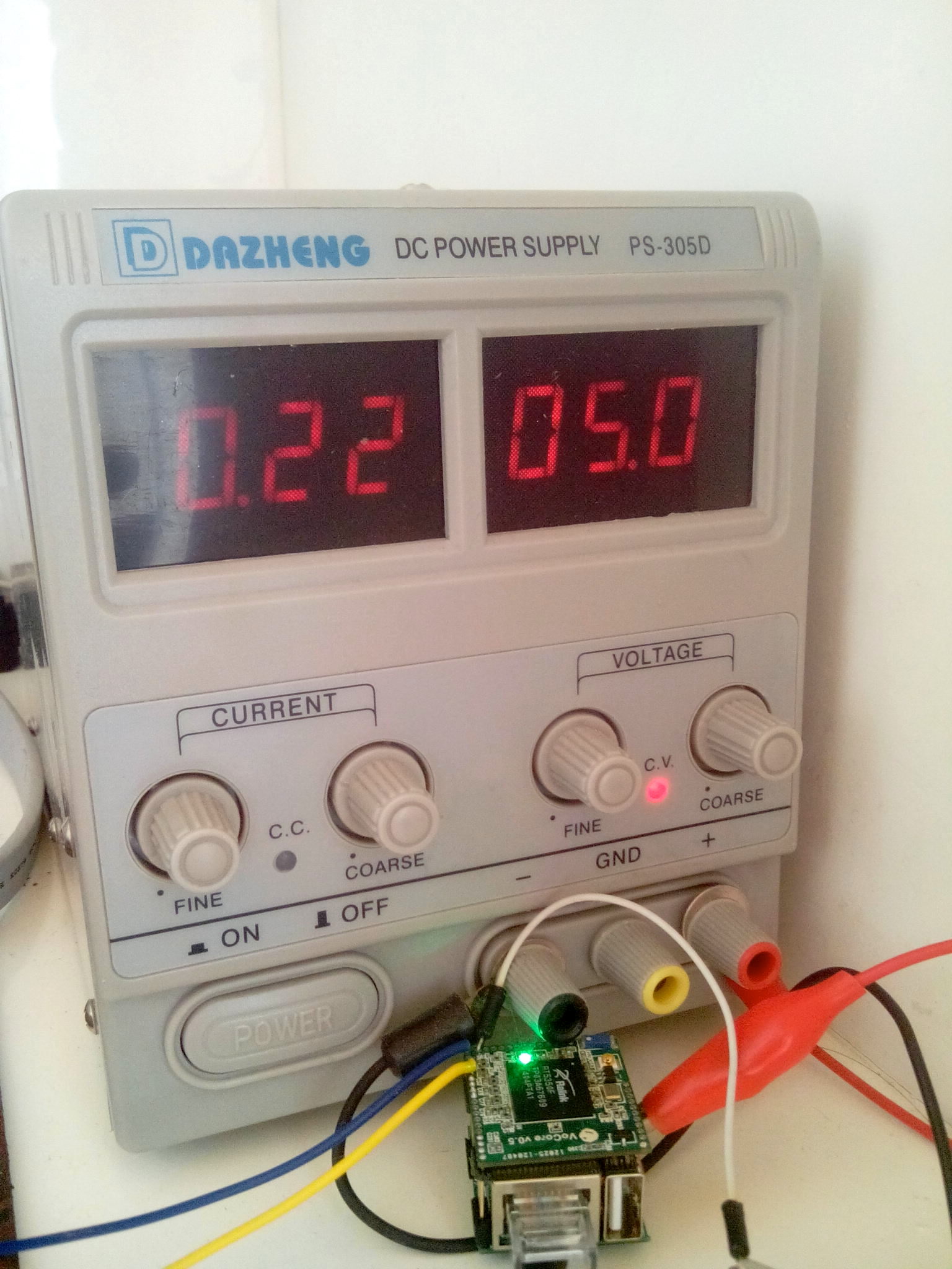
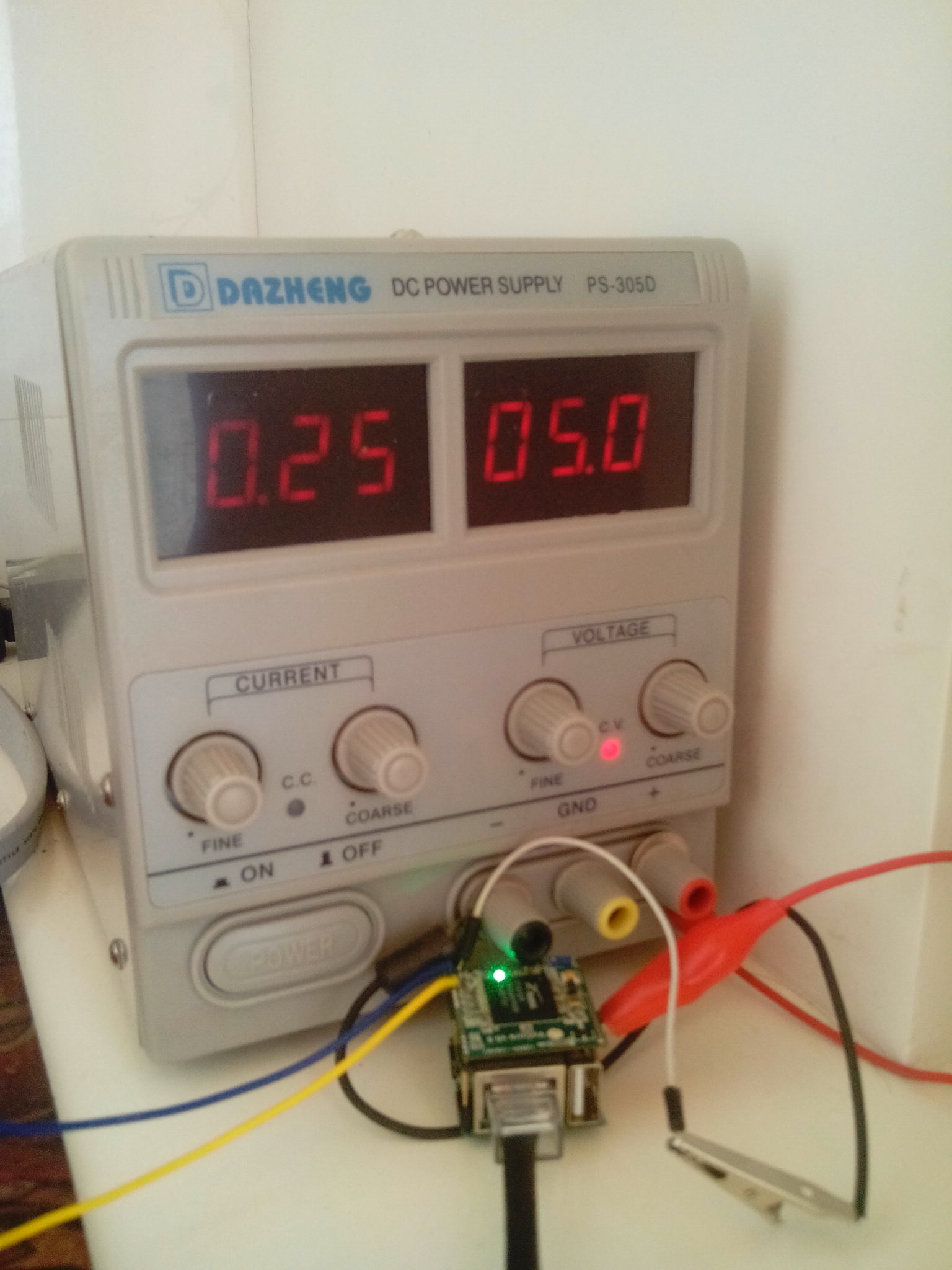
PC is on, download at full speed(240mA~260mA):
The power consume for ethernet is just fair. 🙂
This is its power consume:
5V input, AP+STA mode, ethernet port 0 is on, length is about 3m.
PC is off/no data transfer, power consume(200mA~220mA):
PC is on, download at full speed(240mA~260mA):
The power consume for ethernet is just fair. 🙂
Haha, it works now.
Just unplug it from my router, and connect it to my windows PC(really hate mac removed ethernet interface XD).
Data transfer this way:
My House Router (wifi)-> VoCore (ethernet)-> My PC.
VoCore alloced 192.168.61.190 for my win pc.
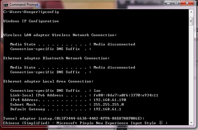
Now I am sending this blog through the VoCore 🙂 The tests move so smoothly.
Later will watch a movie or do something using heavy network load. And put my phone near it as an interfering signal(that is real, once my phone ring, my HDMI monitor just go black and do not work at all! It is about 20cm from the HDMI cable) to check if there is any problem for high frequent data transfer. I have confidence for that, due to the wire is very short(about 300~400mil) and every data pair length is just same(<10mil, but impedance about 80ohm).
Connect dock to ethernet.

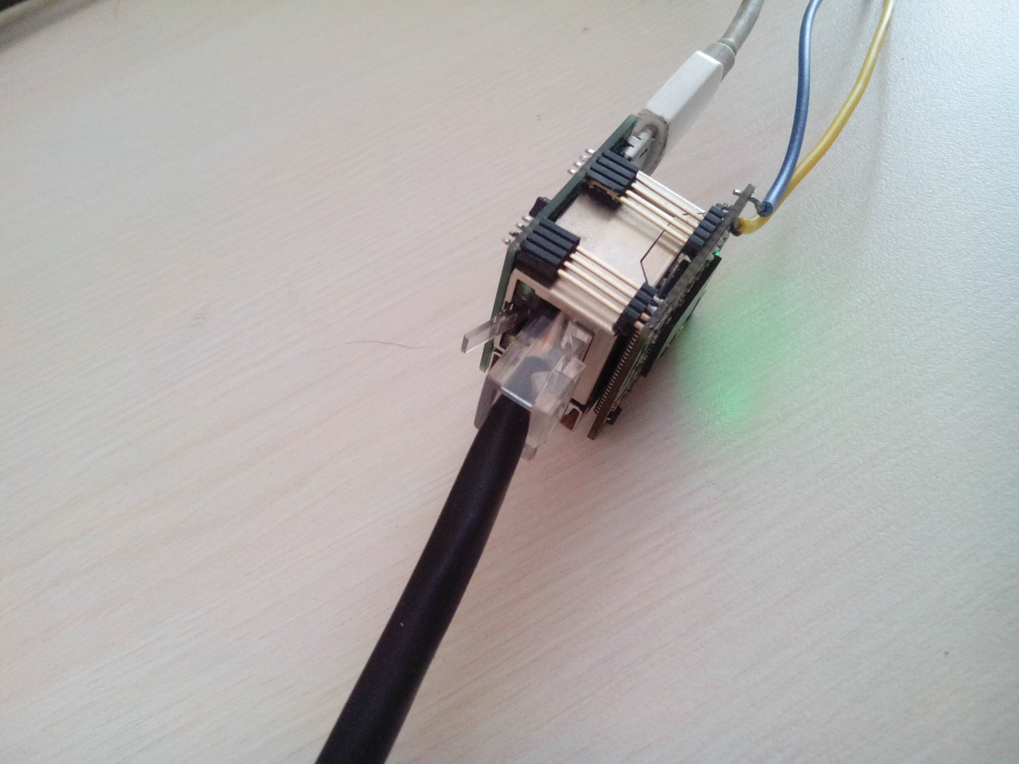
Looks like there is nothing wrong in hardware part.
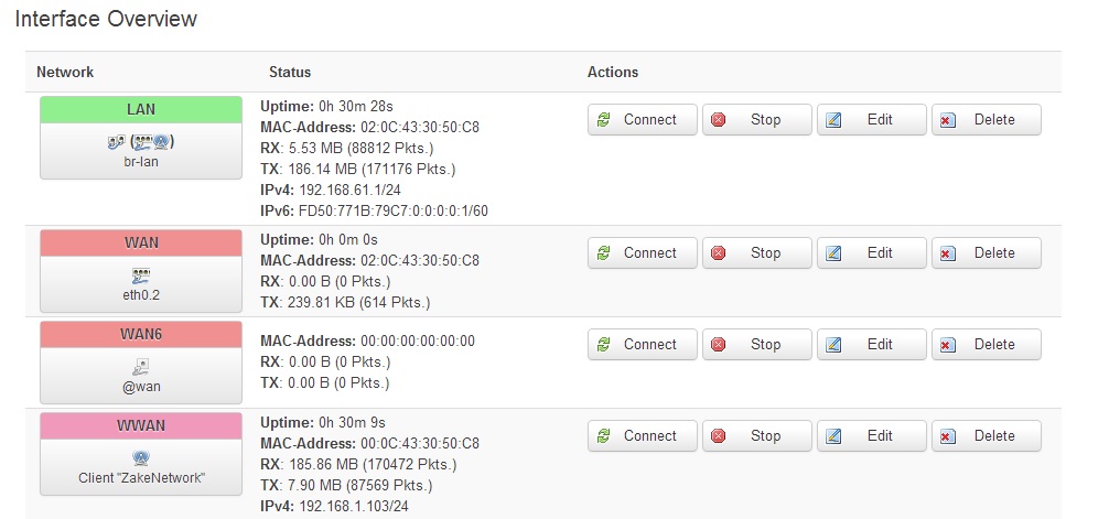
LuCI detected the ethernet port0.
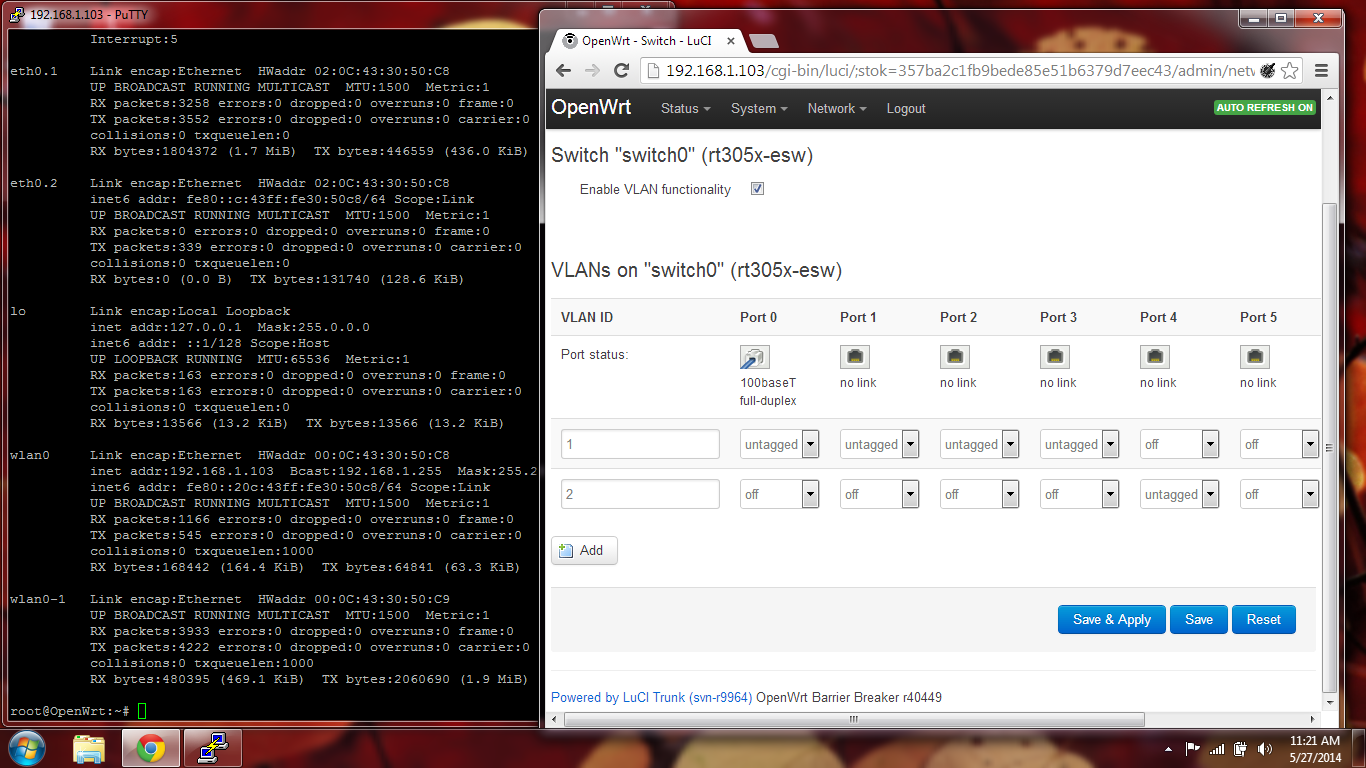
There is something wrong in the software part, I can not connect to the ip which alloced by my house router. VoCore’s AP+STA is still working, but ethernet not. I find the VoCore sta mac and the ethernet mac in my HyFi router DHCP client list.
192.168.1.103 is wwan(sta mode).
192.168.1.102 is the ethernet.

This is ifconfig result.
root@OpenWrt:~# ifconfig
br-lan    Link encap:Ethernet  HWaddr 02:0C:43:30:50:C8
          inet addr:192.168.61.1  Bcast:192.168.61.255  Mask:255.255.255.0
          inet6 addr: fd50:771b:79c7::1/60 Scope:Global
          inet6 addr: fe80::c:43ff:fe30:50c8/64 Scope:Link
          UP BROADCAST RUNNING MULTICAST  MTU:1500  Metric:1
          RX packets:1401 errors:0 dropped:0 overruns:0 frame:0
          TX packets:589 errors:0 dropped:0 overruns:0 carrier:0
          collisions:0 txqueuelen:0
          RX bytes:119829 (117.0 KiB)  TX bytes:117226 (114.4 KiB)

eth0      Link encap:Ethernet  HWaddr 02:0C:43:30:50:C8
          inet6 addr: fe80::c:43ff:fe30:50c8/64 Scope:Link
          UP BROADCAST RUNNING MULTICAST  MTU:1500  Metric:1
          RX packets:4711 errors:0 dropped:0 overruns:0 frame:0
          TX packets:5456 errors:0 dropped:0 overruns:0 carrier:0
          collisions:0 txqueuelen:1000
          RX bytes:2652097 (2.5 MiB)  TX bytes:839633 (819.9 KiB)
          Interrupt:5

eth0.1    Link encap:Ethernet  HWaddr 02:0C:43:30:50:C8
          UP BROADCAST RUNNING MULTICAST  MTU:1500  Metric:1
          RX packets:4708 errors:0 dropped:0 overruns:0 frame:0
          TX packets:4998 errors:0 dropped:0 overruns:0 carrier:0
          collisions:0 txqueuelen:0
          RX bytes:2567133 (2.4 MiB)  TX bytes:622033 (607.4 KiB)

eth0.2    Link encap:Ethernet  HWaddr 02:0C:43:30:50:C8
          inet6 addr: fe80::c:43ff:fe30:50c8/64 Scope:Link
          UP BROADCAST RUNNING MULTICAST  MTU:1500  Metric:1
          RX packets:0 errors:0 dropped:0 overruns:0 frame:0
          TX packets:453 errors:0 dropped:0 overruns:0 carrier:0
          collisions:0 txqueuelen:0
          RX bytes:0 (0.0 B)  TX bytes:176542 (172.4 KiB)

lo        Link encap:Local Loopback
          inet addr:127.0.0.1  Mask:255.0.0.0
          inet6 addr: ::1/128 Scope:Host
          UP LOOPBACK RUNNING  MTU:65536  Metric:1
          RX packets:163 errors:0 dropped:0 overruns:0 frame:0
          TX packets:163 errors:0 dropped:0 overruns:0 carrier:0
          collisions:0 txqueuelen:0
          RX bytes:13566 (13.2 KiB)  TX bytes:13566 (13.2 KiB)

wlan0     Link encap:Ethernet  HWaddr 00:0C:43:30:50:C8
          inet addr:192.168.1.103  Bcast:192.168.1.255  Mask:255.255.255.0
          inet6 addr: fe80::20c:43ff:fe30:50c8/64 Scope:Link
          UP BROADCAST RUNNING MULTICAST  MTU:1500  Metric:1
          RX packets:1948 errors:0 dropped:0 overruns:0 frame:0
          TX packets:1338 errors:0 dropped:0 overruns:0 carrier:0
          collisions:0 txqueuelen:1000
          RX bytes:279153 (272.6 KiB)  TX bytes:332484 (324.6 KiB)

wlan0-1   Link encap:Ethernet  HWaddr 00:0C:43:30:50:C9
          UP BROADCAST RUNNING MULTICAST  MTU:1500  Metric:1
          RX packets:5483 errors:0 dropped:0 overruns:0 frame:0
          TX packets:5848 errors:0 dropped:0 overruns:0 carrier:0
          collisions:0 txqueuelen:1000
          RX bytes:665360 (649.7 KiB)  TX bytes:2902243 (2.7 MiB)
Looks like eth0 is following br-lan 192.168.61.1(same mac), so eth0 can not assigned to 192.168.1.102 auto. The two routers are fighting 😀
If I force eth0 ip to 192.168.1.102, what will happen? I will check later.
For now, the main hardware functions: Ethernet/Wifi/USB/GPIO, have passed two.
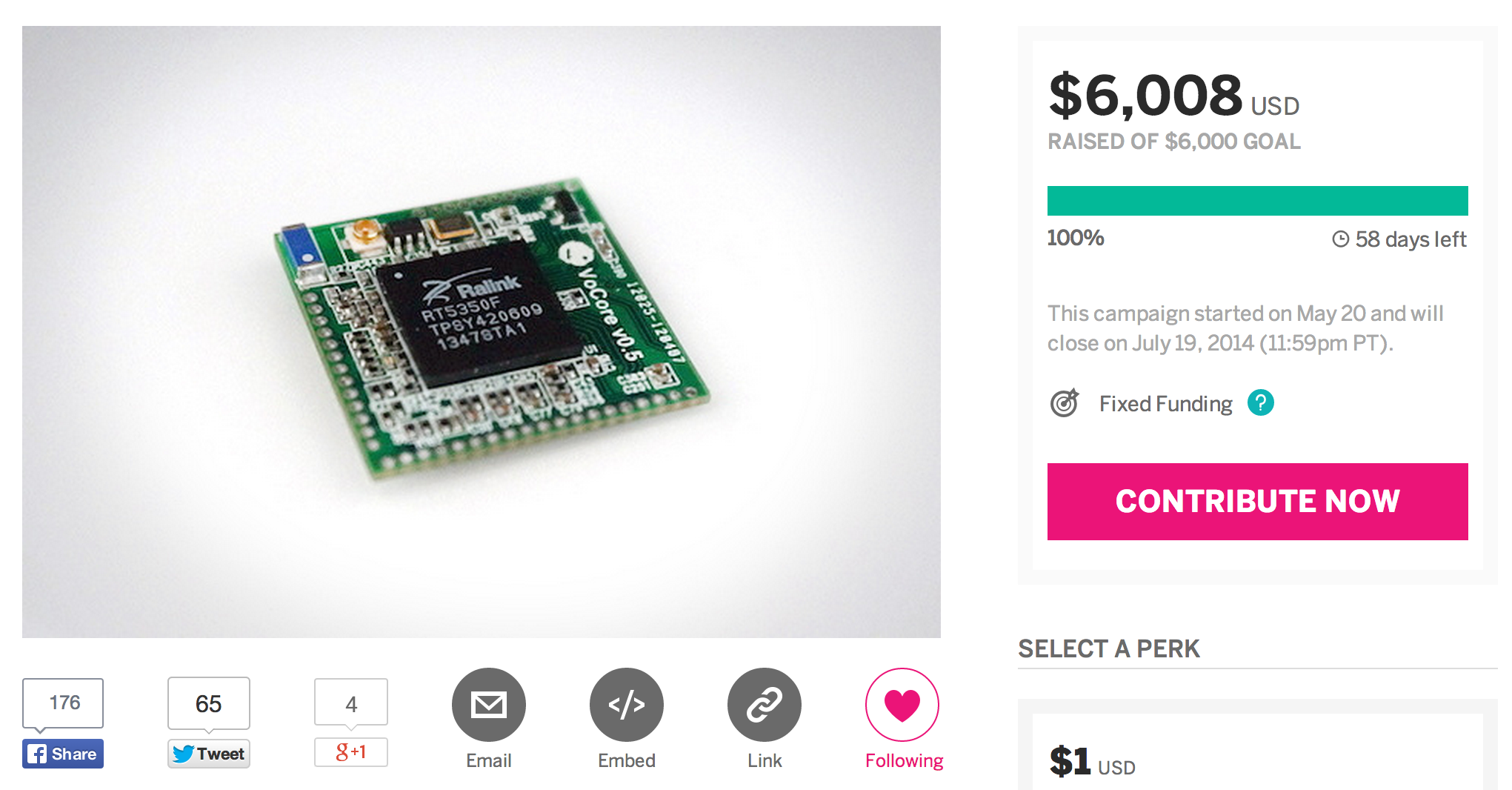
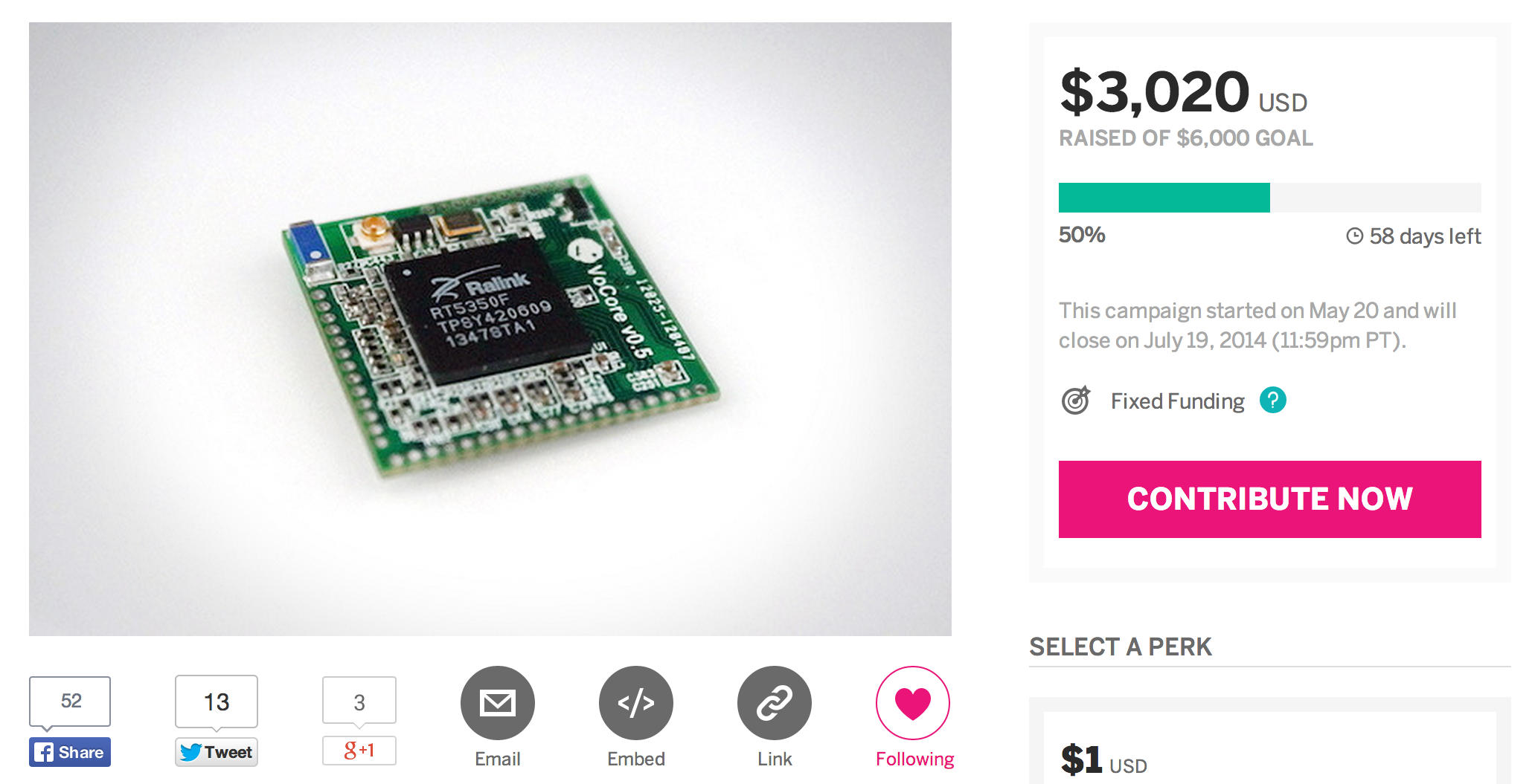
Thank you for everybody support on indiegogo at first 🙂
That campaign on indiegogo is really out of my imagination. I just want to sell about 300 pieces so I can send it to factory.
This article will tell you how to make OpenWrt working on VoCore. In fact, it is not that hard. I do not need to change a word in source code. That is benefited by RT5350 is a stable chip for years and it has already been fully supported by OpenWrt.
First: Prepare a Linux System
MacOS(Unix) could do that too, but it will cost much more time to prepare, just ignore it.
This is my VM(VirtualBox) of debian on my MacOS.
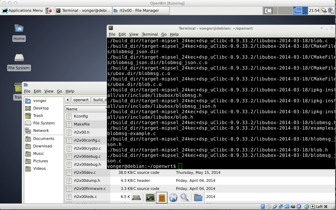
Second: Prepare Tools for OpenWrt
This is easy to be find on Google. I just copy some from other websites.
sudo apt-get install gcc
sudo apt-get install g++
sudo apt-get install binutils
sudo apt-get install patch
sudo apt-get install bzip2
sudo apt-get install flex
sudo apt-get install bison
sudo apt-get install make
sudo apt-get install autoconf
sudo apt-get install gettext
sudo apt-get install unzip
sudo apt-get install subversion
sudo apt-get install libncurses5-dev
sudo apt-get install ncurses-term
sudo apt-get install zlib1g-dev
sudo apt-get install gawk
sudo apt-get install git-core
sudo apt-get install libz-dev
Third: Prepare OpenWrt Source Code
This OpenWrt wiki will help: https://dev.openwrt.org/wiki/GetSource
Fourth: Prepare Feeds for OpenWrt
(LuCI interface is one of the feeds)
Goto openwrt source code folder, then call:
./scripts/feeds update –a
./scripts/feeds install –a
Fifth: Compile OpenWrt
make menuconfig
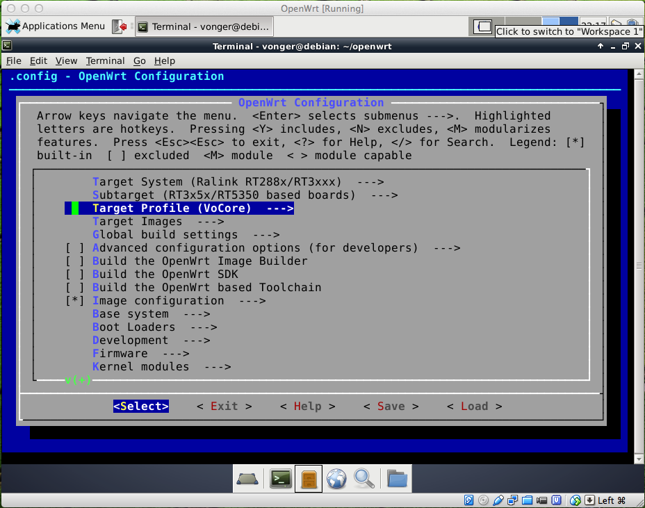
Target System: Ralink RT288x/RT3xxx
RT5350 is based on RT288x
Subtarget: RT3x5x/RT5350 based boards
It is obviously, VoCore is based on RT5350
Target Profile: VoCore
Current OpenWrt source do not have this config yet, will try to commit my VoCore profile to OpenWrt soon. Other RT5350 profiles are compatible with VoCore, for example, before I write VoCore dts, I just use “Poray X8” instead.
Just keep rest of the menuconfig to default, then save & exit, call make…
Have to wait a long time, OpenWrt will download every source code and make everything for you from source code. The Cross Compiled Toolchain will be made from source code too, that is awesome, I have tried to compiled Cross Compiled Toolchain by myself three years ago for S3C2440 board, but failed. 🙂
OpenWrt is really good, the hole process is that complex but there is no error.
Final: Send BIN to VoCore
After compiled openwrt, there is a folder named bin/ramips, there are many bins.
Just ignore most of them, focus on the files named openwrt.XXXXXXXX.sysupgrade.bin.
Send it to VoCore has four ways:
1. I have a USB SPI flash writer, so it is able to write data to flash directly, then solder the flash onto VoCore, that is used for an empty flash or bricked VoCore. If you do not want to solder that, just buy a simple tool that mentioned in my former blog.
NOTIFY: that bin is just firmware data, so we need to combine it with uboot, factory setting then burn it to SPI flash.
2. If there are already boot loader exists, tftp/kermit the bin to firmware.
3. If old firmware exists:
mtd -r write openwrt.XXXXXXXX.sysupgrade.bin firmware
4. JTAG, it might be possible but I did not test.
Addition: Compile Your Own App
Just check this link: http://wiki.openwrt.org/doc/devel/crosscompile
I am lazy, my app on VoCore is just one .c file(such as vof), so just go to ./staging_dir/toolchain-mipsel_24kec+dsp_gcc-4.8-linaro_uClibc-0.9.33.2/bin/ run ./mipsel-openwrt-linux-gcc -g vof.c
OK, that’s all. Hope this will be useful. 🙂
I do not have to worry about the campaign anymore. Now focus on the tech part. 🙂
From tomorrow, everyday I will spend about 1 hour to answer the questions and reply the comment, rest time will all on the Engineer and Test part.
Thank you for everybody support on this campaign!
Here are some questions from indiegogo private message and comment, hopefully this will help you know more about VoCore.
1. Are there SPI pins export?
Only one is exported, it is SPI_CS1, also can be used as GPIO. Rest SPI pins/balls are not exported because they are already taken by SPI flash. Another reason is there is no space for that hole.:D If you have to use SPI interface, please try to jump wire directly from the SPI flash. Good luck 🙂
2. Can I use Li-Battery as power input?
Yes, of course. Li-Battery is about 3.7V~4.3V, and VoCore allowed input voltage range is 3.3V~6.0V, so USB and Li-Battery are both fine to it. Even four 1.2V AA batteries could do that.
3. Why not use BGA SDRAM to make it smaller?
I think I can make it to about 22×23 once using BGA SDRAM, but BGA SDRAM is so expansive, about 5~6USD for one. And 22×23 compared with 25×25 is not a huge difference. So I choose TSOP54 SDRAM.
4. About the heat of CPU.
It is really hot. From my last test, it works around 63C for about 10 days without any error(my house is about 24C, my power is cut off so the test is end there). The feeling of 63C is very hot that you will not want to touch it. 😀 The dock with metal ethernet connector will be designed as a heat sink. Anyway, I think it should be OK to work at 63C or even more, my friend has used RT5350 to make wifi cameras without any heat sink(just be dropped into a metal box to protect it from rain, as he said) for the traffic monitor on Xi’an street about two years ago, the highest temperature of there in summer noon is over 50C. They are still working. 🙂
Thank you! Thank you for everyone support this campaign!
Now go back to work, there still left a lot to do before it release. 🙂
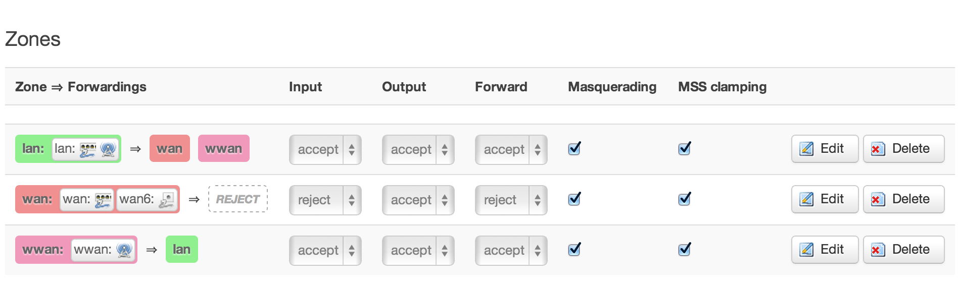
After set to upper setting, it just works. Thanks for joyhope suggestion, it is firewall problem.
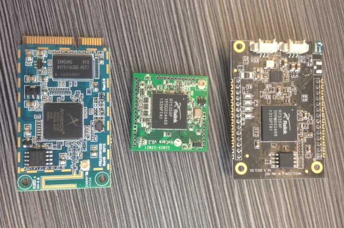
My friend sent me a photo, compared VoCore v0.3 with others. VoCore is the smallest and exported the most GPIOs, of course 🙂
VoCore v0.3 size is 27x27mm but VoCore v0.5 is only 25x25mm, even smaller.
This is my first time to record a video for VoCore, some parts are not very clear, next time will be better 🙂
+5V input, current is about 0.2A when wifi is on. I did not use any power save kernel module or app, amazing! I thought it should be at least 0.25A. :p Its power consume is even less than MT7620A. Wifi output is 100mW.
Youtube: http://youtu.be/uNzgvtOJkmw
Youku(China):http://v.youku.com/v_show/id_XNzE0ODk3NTYw.html
Indiegogo.com: http://igg.me/at/vocore