🙂 So many mess things, delayed the SPI & MicroSD process.
I have tried many many ways recently, finally get some results, still need more check/read/fix etc…
First, I read all the code about SPI and MMC. Also the RT5350F datasheet, SPI part.
Then, I tried to modify that spi-rt2880.c to support SPI1. Thanks for that patch I mentioned in “VoCore: SPI & MicroSD 3” from John, that helps a lot. But no luck, that patch can not work.
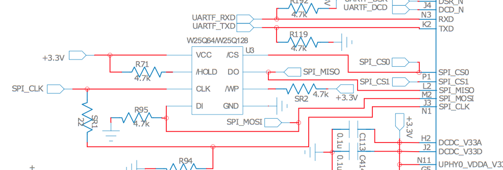
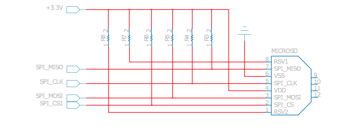
I just think that might be register error, so I connected MISO/MOSI/CS0/CS1 to oscilloscope, and tried every compose of the control/config register.
After many many fails, I got a result, whatever I changed the register, the SPI_CS1 was keeping low. That is abnormal. So when I try to use mmc, I just get many “TX error = -145”, “RX error = -145″…
PS: some other interesting result:
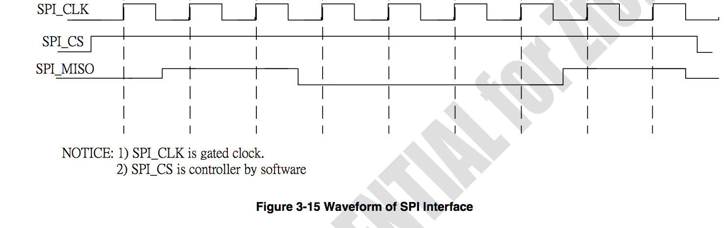
1. I find TXFALLEDGE & RXFALLEDGE register can not be used same time during my test , from my understanding, that is used to control CPHA, should be used same time…weird, need more test.
2. Do not use uboot update the firmware if MicroSD is in the slot. That will cause CRC error once update done and you reboot it.
Then I try to use SPI_CS1 as GPIO, to check if that pin is able to change by code.
When I call “echo 27 > export”, just get such error “This device does not exist”.
I was thinking that must be taken by SPI driver, so just another try “echo 3 > export”(GPIO3 is one in using SPI pin), get a totally different result, system told me it is busy.
That should be driver problem now, and not spi-rt2880 driver problem, when I am reading/fixing the pinmux code. This topic(http://vonger.cn/?topic=rfc-openwrt-support) helps me. (My old plan is to change pinmux code, which is /linux/arch/mips/ralink/rt305x.c and add a new group spics1 to it)
And I find an issue in that rt5350.dtsi. My fix is here, rt5350.dtsi, VOCORE.dts
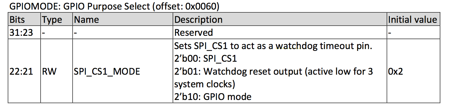
gpio0 is 24 pins but in datasheet that control should only able to control 22 pins. Even we can export 24 gpio from that control but GPIO#22, GPIO#23 can not be use at all.
gpio1 offset is @638, but in datasheet, no such control at all, it should be @660.
Now the GPIO is working.
RX = -145 and TX = -145 disappeared.
But I still get such error every 0.5 seconds. (I guess the driver is trying to detect that SD card, due to we do not have hardware card detect irq)
setup: request speed is too low 400000.
can't not change chip-polarity
That is due to RT5350 min spi speed is 120MHz / 128 = about 1MHz, 400KHz is too low.
And after read the mmc code, that 400KHz is used to compatible the detect process with the old low speed SD card, so it is not that important. Just dirty fix spi-rt2880.c remove that error, and if we find the request spi speed is lower than 1MHz, focus to set it to 1MHz. 🙂 Then the kernel log is quiet.
Finally, another mmc kernel is keeping show itself every 5~30 seconds.
[  353.260000] mmc0: error -22 whilst initialising SDIO card
[  353.270000] mmc0: host doesn't support card's voltages
[  353.280000] mmc0: error -22 whilst initialising SD card
[  353.300000] mmc0: host doesn't support card's voltages
[  353.310000] mmc0: error -22 whilst initialising MMC card
This is easy to remove. VoCore do not support modify SD voltage ranges, so remove the line in VOCORE.dts
voltage-ranges<3300 3300>;
When boot up, there is a warning for that, but no such noise kernel log anymore. 😀
[   15.110000] mmc_spi spi32766.1: OF: voltage-ranges unspecified
[   15.120000] mmc_spi spi32766.1: ASSUMING 3.2-3.4 V slot power
[   15.180000] mmc_spi spi32766.1: SD/MMC host mmc0, no DMA, no WP, no poweroff
From the system log, spi-mmc should work(if my dirty fix works)
[ 0.000000] Linux version 3.10.36 (vonger@vongers-mbp.lan) (gcc version 4.8.3 (OpenWrt/Linaro GCC 4.8-2014.04 r41181) ) #33 Thu Jul 31 16:15:45 CST 2014
[ 0.000000] SoC Type: Ralink RT5350 id:1 rev:3
[ 0.000000] bootconsole [early0] enabled
[ 0.000000] CPU revision is: 0001964c (MIPS 24KEc)
[ 0.000000] MIPS: machine is VoCore
[ 0.000000] Determined physical RAM map:
[ 0.000000] memory: 02000000 @ 00000000 (usable)
[ 0.000000] Initrd not found or empty - disabling initrd
[ 0.000000] Zone ranges:
[ 0.000000] Normal [mem 0x00000000-0x01ffffff]
[ 0.000000] Movable zone start for each node
[ 0.000000] Early memory node ranges
[ 0.000000] node 0: [mem 0x00000000-0x01ffffff]
[ 0.000000] Primary instruction cache 32kB, VIPT, 4-way, linesize 32 bytes.
[ 0.000000] Primary data cache 16kB, 4-way, VIPT, no aliases, linesize 32 bytes
[ 0.000000] Built 1 zonelists in Zone order, mobility grouping on. Total pages: 8128
[ 0.000000] Kernel command line: console=ttyS0,57600 rootfstype=squashfs,jffs2
[ 0.000000] PID hash table entries: 128 (order: -3, 512 bytes)
[ 0.000000] Dentry cache hash table entries: 4096 (order: 2, 16384 bytes)
[ 0.000000] Inode-cache hash table entries: 2048 (order: 1, 8192 bytes)
[ 0.000000] Writing ErrCtl register=00019e38
[ 0.000000] Readback ErrCtl register=00019e38
[ 0.000000] Memory: 29352k/32768k available (2132k kernel code, 3416k reserved, 545k data, 200k init, 0k highmem)
[ 0.000000] SLUB: HWalign=32, Order=0-3, MinObjects=0, CPUs=1, Nodes=1
[ 0.000000] NR_IRQS:256
[ 0.000000] CPU Clock: 360MHz
[ 0.000000] Calibrating delay loop... 239.61 BogoMIPS (lpj=1198080)
[ 0.070000] pid_max: default: 32768 minimum: 301
[ 0.070000] Mount-cache hash table entries: 512
[ 0.080000] pinctrl core: initialized pinctrl subsystem
[ 0.090000] NET: Registered protocol family 16
[ 0.140000] bio: create slab at 0
[ 0.150000] rt2880_gpio 10000600.gpio: registering 22 gpios
[ 0.160000] rt2880_gpio 10000600.gpio: registering 22 irq handlers
[ 0.170000] rt2880_gpio 10000660.gpio: registering 6 gpios
[ 0.180000] rt2880_gpio 10000660.gpio: registering 6 irq handlers
[ 0.190000] Switching to clocksource MIPS
[ 0.200000] NET: Registered protocol family 2
[ 0.210000] TCP established hash table entries: 512 (order: 0, 4096 bytes)
[ 0.230000] TCP bind hash table entries: 512 (order: -1, 2048 bytes)
[ 0.240000] TCP: Hash tables configured (established 512 bind 512)
[ 0.250000] TCP: reno registered
[ 0.260000] UDP hash table entries: 256 (order: 0, 4096 bytes)
[ 0.270000] UDP-Lite hash table entries: 256 (order: 0, 4096 bytes)
[ 0.280000] NET: Registered protocol family 1
[ 0.290000] rt-timer 10000100.timer: maximum frequncy is 7324Hz
[ 0.340000] squashfs: version 4.0 (2009/01/31) Phillip Lougher
[ 0.360000] jffs2: version 2.2 (NAND) (SUMMARY) (LZMA) (RTIME) (CMODE_PRIORITY) (c) 2001-2006 Red Hat, Inc.
[ 0.380000] msgmni has been set to 57
[ 0.390000] io scheduler noop registered
[ 0.390000] io scheduler deadline registered (default)
[ 0.420000] gpio-export gpio-export.4: 19 gpio(s) exported
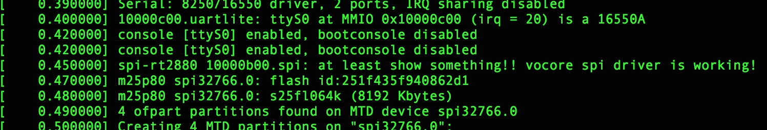
[ 0.430000] Serial: 8250/16550 driver, 2 ports, IRQ sharing disabled
[ 0.450000] 10000c00.uartlite: ttyS0 at MMIO 0x10000c00 (irq = 20) is a 16550A
[ 0.470000] console [ttyS0] enabled, bootconsole disabled
[ 0.470000] console [ttyS0] enabled, bootconsole disabled
[ 0.500000] m25p80 spi32766.0: unique id: 21543693050863d1
[ 0.510000] m25p80 spi32766.0: w25q64 (8192 Kbytes)
[ 0.520000] 4 ofpart partitions found on MTD device spi32766.0
[ 0.530000] Creating 4 MTD partitions on "spi32766.0":
[ 0.540000] 0x000000000000-0x000000030000 : "uboot"
[ 0.550000] 0x000000030000-0x000000040000 : "uboot-env"
[ 0.570000] 0x000000040000-0x000000050000 : "factory"
[ 0.580000] 0x000000050000-0x000000800000 : "firmware"
[ 0.600000] 0x00000013fc33-0x000000800000 : "rootfs"
[ 0.610000] mtd: partition "rootfs" must either start or end on erase block boundary or be smaller than an erase block -- forcing read-only
[ 0.640000] mtd: device 4 (rootfs) set to be root filesystem
[ 0.650000] mtd: partition "rootfs_data" created automatically, ofs=0x370000, len=0x490000
[ 0.660000] 0x000000370000-0x000000800000 : "rootfs_data"
[ 0.690000] eth0: done loading
[ 0.700000] rt3xxx-usbphy ubsphy.3: loaded
[ 0.710000] rt2880_wdt 10000120.watchdog: Initialized
[ 0.720000] TCP: cubic registered
[ 0.730000] NET: Registered protocol family 17
[ 0.740000] 8021q: 802.1Q VLAN Support v1.8
[ 0.760000] VFS: Mounted root (squashfs filesystem) readonly on device 31:4.
[ 0.780000] Freeing unused kernel memory: 200K (8029e000 - 802d0000)
procd: Console is alive
procd: - watchdog -
[ 7.190000] usbcore: registered new interface driver usbfs
[ 7.200000] usbcore: registered new interface driver hub
[ 7.210000] usbcore: registered new device driver usb
[ 7.240000] SCSI subsystem initialized
[ 7.260000] ehci_hcd: USB 2.0 'Enhanced' Host Controller (EHCI) Driver
[ 7.280000] ehci-platform: EHCI generic platform driver
[ 7.490000] rt3xxx-usbphy ubsphy.3: remote usb device wakeup disabled
[ 7.500000] rt3xxx-usbphy ubsphy.3: UTMI 16bit 30MHz
[ 7.510000] ehci-platform 101c0000.ehci: EHCI Host Controller
[ 7.520000] ehci-platform 101c0000.ehci: new USB bus registered, assigned bus number 1
[ 7.540000] ehci-platform 101c0000.ehci: irq 26, io mem 0x101c0000
[ 7.570000] ehci-platform 101c0000.ehci: USB 2.0 started, EHCI 1.00
[ 7.580000] hub 1-0:1.0: USB hub found
[ 7.590000] hub 1-0:1.0: 1 port detected
procd: - preinit -
[ 8.830000] rt305x-esw 10110000.esw: link changed 0x00
Press the [f] key and hit [enter] to enter failsafe mode
Press the [1], [2], [3] or [4] key and hit [enter] to select the debug level
jffs2 is not ready - marker found
procd: - early -
procd: - watchdog -
procd: - ubus -
procd: - init -
Please press Enter to activate this console.
[ 14.620000] NET: Registered protocol family 10
[ 14.650000] nf_conntrack version 0.5.0 (461 buckets, 1844 max)
[ 14.680000] ip6_tables: (C) 2000-2006 Netfilter Core Team
[ 14.710000] Loading modules backported from Linux version master-2014-05-22-0-gf2032ea
[ 14.730000] Backport generated by backports.git backports-20140320-37-g5c33da0
[ 14.750000] ip_tables: (C) 2000-2006 Netfilter Core Team
[ 14.830000] xt_time: kernel timezone is -0000
[ 14.880000] cfg80211: Calling CRDA to update world regulatory domain
[ 14.890000] cfg80211: World regulatory domain updated:
[ 14.900000] cfg80211: DFS Master region: unset
[ 14.910000] cfg80211: (start_freq - end_freq @ bandwidth), (max_antenna_gain, max_eirp), (dfs_cac_time)
[ 14.930000] cfg80211: (2402000 KHz - 2472000 KHz @ 40000 KHz), (N/A, 2000 mBm), (N/A)
[ 14.950000] cfg80211: (2457000 KHz - 2482000 KHz @ 40000 KHz), (N/A, 2000 mBm), (N/A)
[ 14.960000] cfg80211: (2474000 KHz - 2494000 KHz @ 20000 KHz), (N/A, 2000 mBm), (N/A)
[ 14.980000] cfg80211: (5170000 KHz - 5250000 KHz @ 80000 KHz), (N/A, 2000 mBm), (N/A)
[ 15.000000] cfg80211: (5735000 KHz - 5835000 KHz @ 80000 KHz), (N/A, 2000 mBm), (N/A)
[ 15.010000] cfg80211: (57240000 KHz - 63720000 KHz @ 2160000 KHz), (N/A, 0 mBm), (N/A)
[ 15.110000] mmc_spi spi32766.1: OF: voltage-ranges unspecified
[ 15.120000] mmc_spi spi32766.1: ASSUMING 3.2-3.4 V slot power
[ 15.180000] mmc_spi spi32766.1: SD/MMC host mmc0, no DMA, no WP, no poweroff
[ 15.210000] PPP generic driver version 2.4.2
[ 15.230000] NET: Registered protocol family 24
[ 15.290000] ieee80211 phy0: rt2x00_set_rt: Info - RT chipset 5350, rev 0500 detected
[ 15.300000] ieee80211 phy0: rt2x00_set_rf: Info - RF chipset 5350 detected
[ 27.060000] jffs2_scan_eraseblock(): End of filesystem marker found at 0x0
[ 27.090000] jffs2_build_filesystem(): unlocking the mtd device... done.
[ 27.100000] jffs2_build_filesystem(): erasing all blocks after the end marker... [ 30.050000] device eth0.1 entered promiscuous mode
[ 30.060000] device eth0 entered promiscuous mode
[ 30.090000] br-lan: port 1(eth0.1) entered forwarding state
[ 30.100000] br-lan: port 1(eth0.1) entered forwarding state
[ 32.100000] br-lan: port 1(eth0.1) entered forwarding state
Will do test tomorrow 😀
Some necessary files: spi-rt2880.c (some code is from John’s patch)