[embedyt]https://www.youtube.com/watch?v=Oo4pRXG5r_c[/embedyt]
This video is in Portuguese, better to enable Google translate and subtitle. A very nice video, clear than mine. 🙂
[embedyt]https://www.youtube.com/watch?v=Oo4pRXG5r_c[/embedyt]
This video is in Portuguese, better to enable Google translate and subtitle. A very nice video, clear than mine. 🙂
1. Switch port0 between “wan” and “lan”
change in VoCore2, /etc/config/network, first vlan is lan ports, second vlan is wan port, put 0 into second one, port0 will become lan port.
config switch_vlan
...
...
    option ports '0 2 3 4 6t'


config switch_vlan
...
...
    option ports '1 6t'
2. Restart wifi in console.
wifi
3. Clean memory of VoCore2 for long time usage.
sync && echo 3 > /proc/sys/vm/drop_caches
4. Play radio with VoCore2 Ultimate
(sleep 5;wget -O - http://icecast.cogecomedia.com:8000/chmp.mp3 | madplay -)&
(Canada Radio 🙂
5. Add password for UART console.
modify /etc/inittab

::askconsole:/bin/ash --login
------------------------------
::askconsole:/bin/login
note: make sure busybox enable login command when compile busybox.
6. Windows7 or lower system can not install driver for USB2TTL
check this link: Connecting to the serial console on Windows 7
Special Thanks
Patrick Coutu (contribute 3, 4)
Noble Pepper (contribute 6)
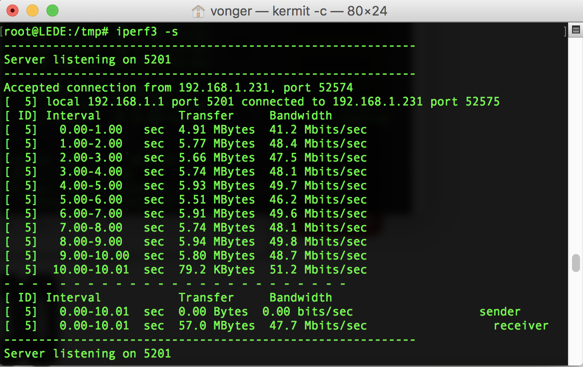
LEDE wifi speed test: one antenna avarage is 47Mb/s, not bad but still have improve space. 🙂
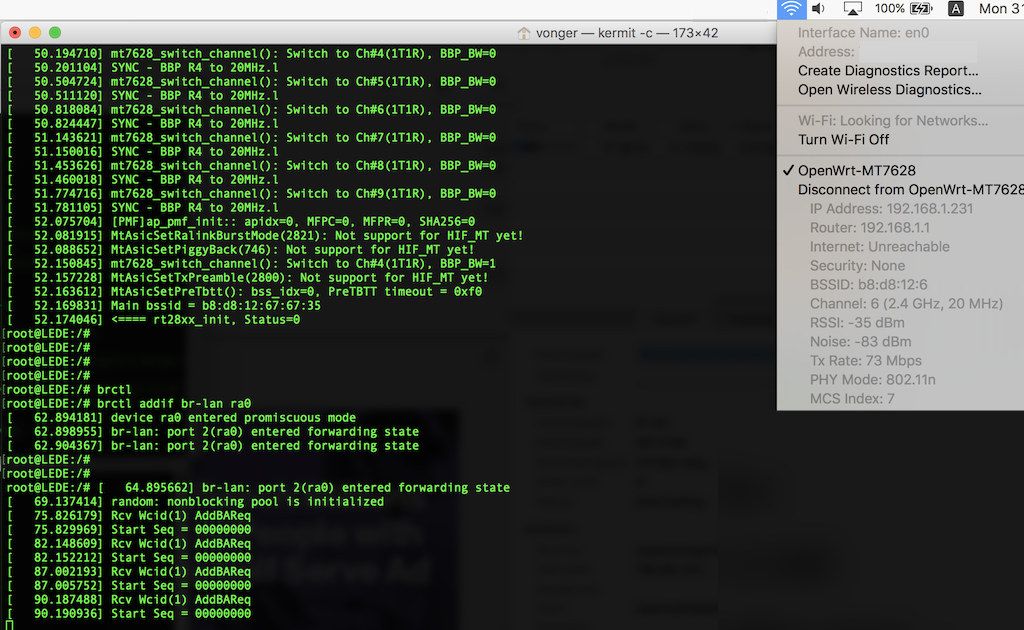
Wahahaha, the driver is working now 🙂
I find the missed command, to make it work, we need call:
brctl addif br-lan ra0
ifconfig ra0 up
Next, let’s unlock the monitor mode.
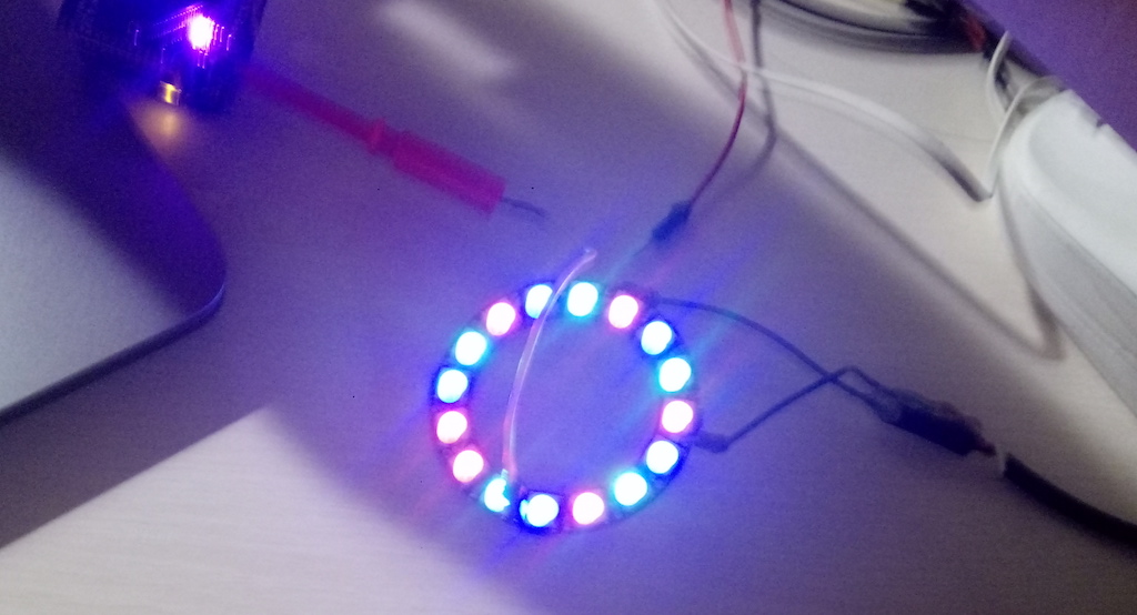
Now we can use VoCore2 control WS2812B based LED belt 🙂 Hope this helps you make a beautiful house.
This is a “big” project for me, it contains three parts.
“There is no secret in the source code.”
First is Linux Driver Code: ws2812b.c, put it into Linux kernel and add it to Makefile and Kconfig, also enable gdma at VOCORE2.dts, compile. If it works normal, it will create a system file at /sys/devices/10000000.palmbus/10002800.gdma/update
You can try “echo aaaa > /sys/devices/10000000.palmbus/10002800.gdma/update”, I2S_SDO will output wave like this:
![]()
PS: actually I2S received data is “aaaa\r”
Then API Source Code: ws2812_api
ws2812_reset(): call this to turn all LEDs off RGB(0,0,0).
ws2812_set(int *color, int size): set leds colors. example: you have 16 WS2812B in a line, you want to set them to different color, code should be like this (include ws2812.h)
		int color[] = {0x080000, 0x000800, 0x000008,
		               0x080000, 0x000800, 0x000008,
		               0x080000, 0x000800, 0x000008,
		               0x080000, 0x000800, 0x000008,
		               0x080000, 0x000800, 0x000008,
		               0x080000,
		              };
		ws2812_set(color, sizeof(color) / sizeof(int));
For more details, check unit test code at the end of ws2812.c.
The head photo is from this code 🙂 For me everything works well.
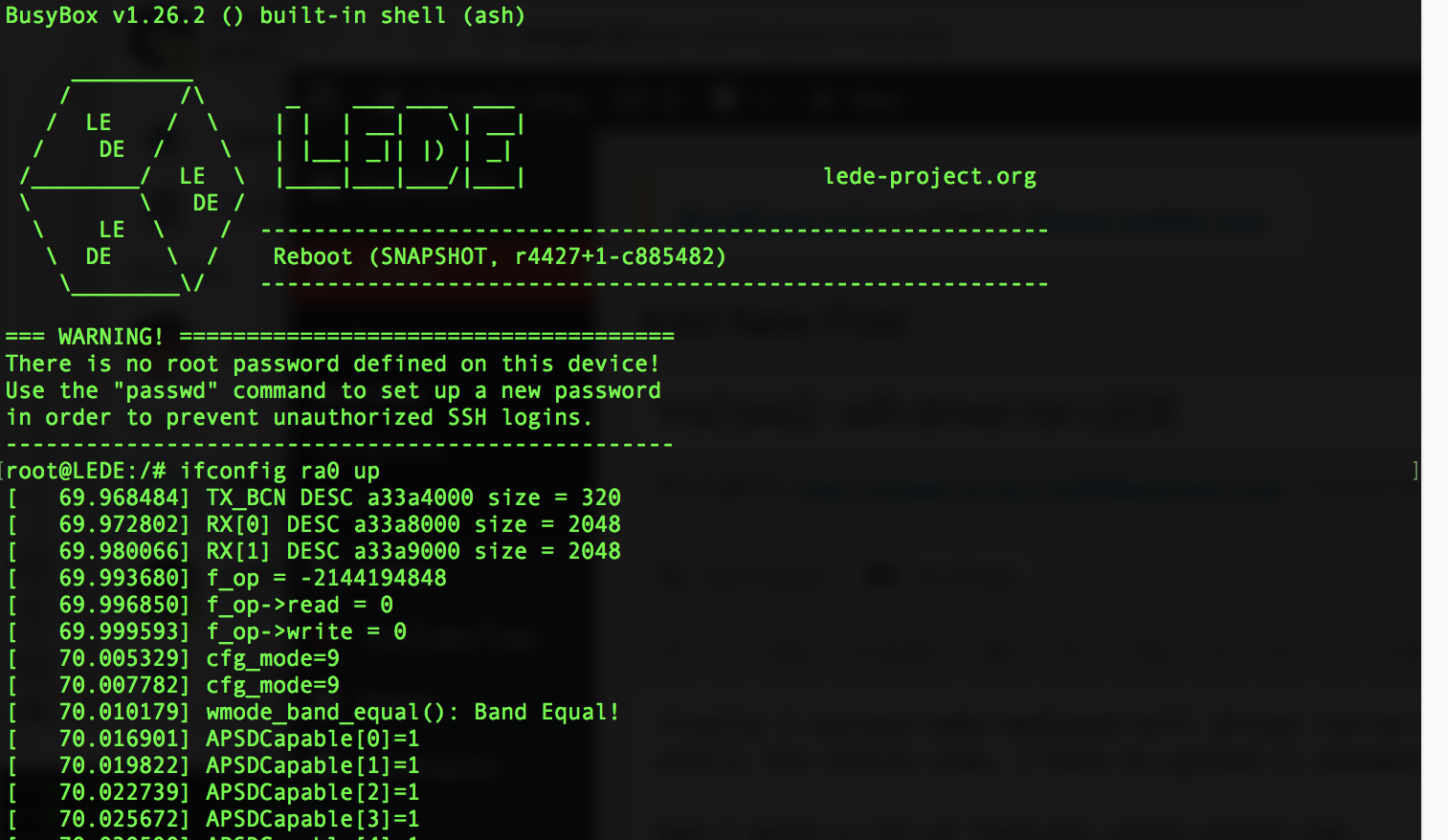
Last time I have success make the driver work, but it is not done.
Currently the log is like this, call “ifconfig ra0 up”
......
[  113.627999] mt7628_switch_channel(): Switch to Ch#9(1T1R), BBP_BW=0
[  113.634363] SYNC - BBP R4 to 20MHz.l
[  113.935695] [PMF]ap_pmf_init:: apidx=0, MFPC=0, MFPR=0, SHA256=0
[  113.941908] MtAsicSetRalinkBurstMode(2821): Not support for HIF_MT yet!
[  113.948644] MtAsicSetPiggyBack(746): Not support for HIF_MT yet!
[  113.982402] mt7628_switch_channel(): Switch to Ch#4(1T1R), BBP_BW=1
[  113.988785] MtAsicSetTxPreamble(2800): Not support for HIF_MT yet!
[  113.995163] MtAsicSetPreTbtt(): bss_idx=0, PreTBTT timeout = 0xf0
[  114.001379] Main bssid = b8:d8:12:67:5f:b5
[  114.005593] <==== rt28xx_init, Status=0
But I stopped here, I can find the SSID in my computer wifi list, but I can not connect to it, the icon on computer(macbook) is keeping in “connecting” status. I think I must miss some key steps, normal log should be like this.
[  449.410000] <==== rt28xx_init, Status=0
[  449.540000] device ra0 entered promiscuous mode
[  449.540000] br-lan: port 2(ra0) entered forwarding state
[  449.550000] br-lan: port 2(ra0) entered forwarding state
[  451.550000] br-lan: port 2(ra0) entered forwarding state
After ifconfig up, there is no log about ra0 entered forwarding state :p I am a noob again, haha. If you reader happen to know my mystery issue, please leave a message to this post 🙂
Here is my compiled mt7628.ko for lede, do not depends on other kernel module, my command: "insmod mt7628.ko" and "ifconfig ra0 up" should make it work.
Also mediatek driver do not support openwrt uci interface, Linkit driver is using iwpriv to setup everything, another way is to use a config file in /etc/wireless/mt7628/mt7628.dat.
You can download here and copy to your lede.mt7628.dat
PS: the developing version lede is broken for VoCore2, lol, I guess somebody modify uart2 interrupt, now uart2 can not input any command to console, only able to output log to console, sad 🙂
Finally I success make mediatek wifi driver run on LEDE 🙂 But mediatek do not allow to public the source code, I have to upload it somewhere as blob.
Now I guess a lot of features could unlock now.
1. monitor mode.
LEDE mt76 driver is very slow, but mediatek official driver is fast and stable.
2. more than one ssid.
we can create one ssid named VoCore2 and one named VoCore2-Guest for host and guest. It supports up to 16 ssid.
3. low level wifi control.
normally we use this for certification like FCC, KC…Last time I have to use mediatek openwrt, but now we can directly use LEDE.
[embedyt] https://www.youtube.com/watch?v=TSBWX0yvuKE[/embedyt]
Now the LCD works 🙂
I change CPOL/CHPA from mode 0 to mode 3, that SPI wave shape is correct now.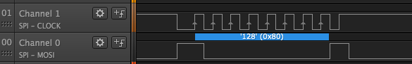
Also finish a simple app to drive the TFT, refresh full screen from red/green/blue pixel by pixel. Download source code here: tft.c
From my test, the LCD screen max speed is around 3.8MHz (speed=49), can not reach 6MHz, that’s bad news. We can not use it as a game display but only for low frame rate usage — such as digital photo display, display 480×320 picture will take around 1~2 seconds.
Here is the real time video:
[embedyt] https://www.youtube.com/watch?v=0QBSJxizE6M[/embedyt]
I called the following command in this video(tft is compiled from the source):
tft r 49
tft g 49
tft b 49
Power consume is 5V 0.21~0.23A, a little more than 1 watt, 10000mAh battery should make it last over 30 hours. 🙂
Next blog I will update the source code a little to make it display some real photos.
Recently six months flash chip price is almost doubled, it is a key chip of VoCore. The world is sick, nobody invest the chip factory and real economy…It is almost ten years since 2008, hope everything goes well.
Maybe its time to consider remove flash from VoCore and add a tf card slot 😂
I think it is possible, all we need in the flash chip is the bootloader, it is around 128KB, can be store in 1Mb flash, that one price is doubled but still acceptable 🙂
Bootloader will need add two drivers, one read from USB disk, one read from sd card. disk format is a problem, we can make bootloader use SD card first 16MB as the old flash, and read Linux from there.
Actually many customized u-boot has already done that. It’s time!