The three days I have made a great process.
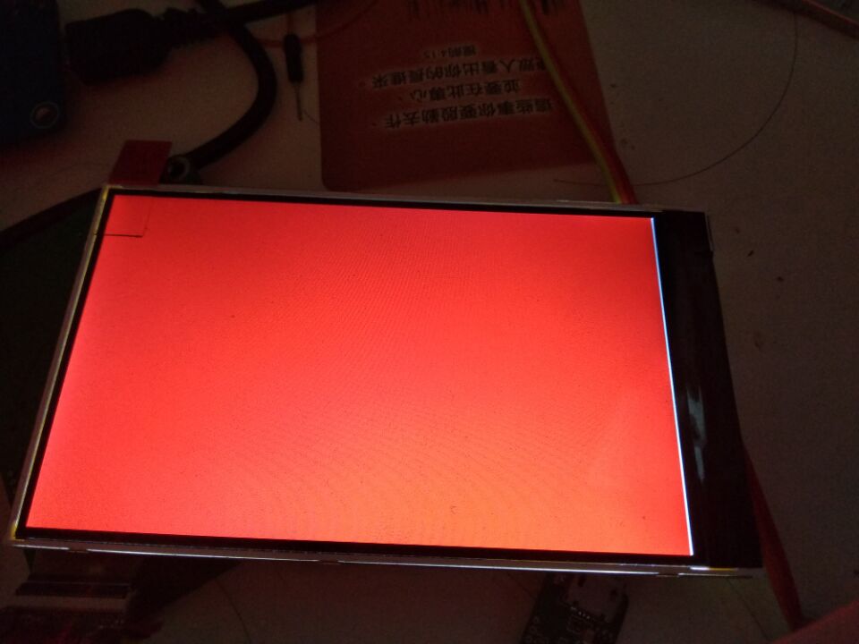
Backlight PWM control is working now and the screen can reach at least 24fps. I checked send 144 frames time is 5.8s.
This is a simple code I do the test:
first create three random pictures, and then use libusb bulk mode send it to the screen. Totally 48 loops and every loops send three “true color” pictures. Also a video of the test is attached.
#define FRAMESIZE		((unsigned int)800 * 480 * 3)

...


    buf1 = (unsigned char *)malloc(FRAMESIZE);
    for (i = 0; i < FRAMESIZE; i++)
        buf1[i] = (unsigned char)(rand() & 0xff);
    buf2 = (unsigned char *)malloc(FRAMESIZE);
    for (i = 0; i < FRAMESIZE; i++)
        buf2[i] = (unsigned char)(rand() & 0xff);
    buf3 = (unsigned char *)malloc(FRAMESIZE);
    for (i = 0; i < FRAMESIZE; i++)
        buf3[i] = (unsigned char)(rand() & 0xff);

    for(i = 0; i < 48; i++) {
        // send to out endpoint 2.
        code = libusb_bulk_transfer(handle, 0x02, buf1, FRAMESIZE, &trans, 1000);
        if (code) {
            printf("output endpoint2 error code: %d, %d\n", code, i);
            return code;
        }
        code = libusb_bulk_transfer(handle, 0x02, buf2, FRAMESIZE, &trans, 1000);
        if (code) {
            printf("output endpoint2 error code: %d, %d\n", code, i);
            return code;
        }
        code = libusb_bulk_transfer(handle, 0x02, buf3, FRAMESIZE, &trans, 1000);
        if (code) {
            printf("output endpoint2 error code: %d, %d\n", code, i);
            return code;
        }
    }
The screen is 80% done, I think I can fix rest bugs very soon 🙂
[embedyt]https://youtu.be/zA81GuyK6qY[/embedyt]