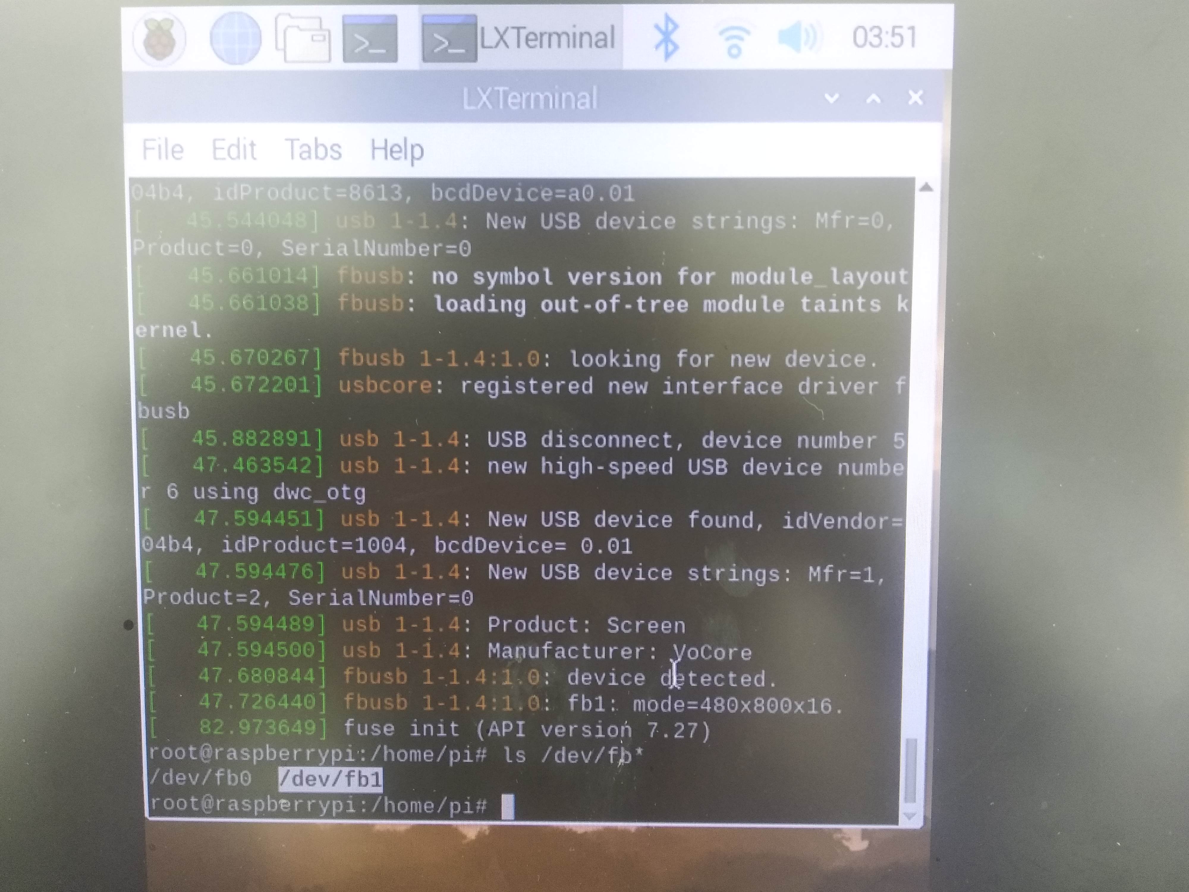
Today I make some progress on i2c, because I want to use VoCore2 to driver a IR camera, its type is MLX90640, but i2c-gpio spends too much CPU and old hardware driver i2c-mt7621 can not get correct data.
i2c-gpio spends a lot of CPU time because it is using busy wait between every bit, so if I want to get MLX90640 at 8fps, it will need 800byte x 8bit x 8 = 51.2KHz, emm, currently i2c-gpio max speed is 250KHz, so it will take over 20% CPU…not a good choice.
i2c-mt7621 driver is using auto mode of mt7628’s i2c hardware, but that ‘auto’ mode only allow send byte one by one. (PS: what stupid auto mode…not auto at all…maybe something wrong?), it is much faster and less cpu taken than i2c-gpio mode, but between two bytes it has a big gap, around 50us, it is not acceptable by MLX90640, so if using this driver, I will never get 90640 correct data.
I have to find some new way… When I look into datasheet, I find mt7628 i2c also support a “sequence” mode which is able to send up to 8 bytes one time, and also get every byte status bit (status bit is NACK, ACK), this is perfect.
After several tries, I make it work successfully.
Here is the core part of code, raw patch uploaded to github.com/vonger/vocore2.git, replace old 0045 patch in openwrt.
static int mtk_i2c_trigger(struct mtk_i2c *i2c, u32 mode, u32 c)
{
	u32 val, reg = 0;

	val = (mode << SM0_MODE_SHIFT) | ((c - 1) << PGLEN_SHIFT) | SM0_TRI_BUSY;
	iowrite32(val, i2c->base + REG_SM0CTL1);

	usleep_range(i2c->delay * c, i2c->delay * c + 50);
	if (mode == SM0_MODE_WRITE || mode == SM0_MODE_READ_ACK) {
		reg = ioread32(i2c->base + REG_SM0CTL1);
		val = (reg >> ACK_SHIFT) & ACK_MASK;
		if (val == 0)
			return -1;
	}
	return 0;
}

static int mtk_i2c_master_read(struct mtk_i2c *i2c, struct i2c_msg *cur)
{
	int used = 0;

	iowrite32(cur->addr * 2 + 1, i2c->base + REG_SM0D0);
	if (mtk_i2c_trigger(i2c, SM0_MODE_WRITE, 1) < 0)
		return -1;

	while (used < cur->len) {
		int size = min(cur->len - used, 8);

		if (used + size == cur->len)	/* last page, send NAK */
			mtk_i2c_trigger(i2c, SM0_MODE_READ_NACK, size);
		else
			mtk_i2c_trigger(i2c, SM0_MODE_READ_ACK, size);

		memcpy(cur->buf + used, i2c->base + REG_SM0D0, size);
		used += size;
	}
	return used;
}

static int mtk_i2c_master_write(struct mtk_i2c *i2c, struct i2c_msg *cur)
{
	int used = 0;

	iowrite32(cur->addr * 2, i2c->base + REG_SM0D0);
	if (mtk_i2c_trigger(i2c, SM0_MODE_WRITE, 1) < 0)
		return -1;

	while (used < cur->len) {
		int size = min(cur->len - used, 8);
		memcpy(i2c->base + REG_SM0D0, cur->buf + used, size);
		mtk_i2c_trigger(i2c, SM0_MODE_WRITE, size);
		used += size;
	}
	return used;
}

static int mtk_i2c_master_xfer(struct i2c_adapter *a, struct i2c_msg *m, int c)
{
	struct mtk_i2c *i2c = i2c_get_adapdata(a);
	int i;

	for (i = 0; i < c; i++) {
		if (m[i].flags & I2C_M_TEN)
			return -EINVAL;
		mtk_i2c_trigger(i2c, SM0_MODE_START, 1);
		if ((m + i)->flags & I2C_M_RD) {
			if (mtk_i2c_master_read(i2c, m + i) < 0)
				break;
		} else {
			if (mtk_i2c_master_write(i2c, m + i) < 0)
				break;
		}
	}
	mtk_i2c_trigger(i2c, SM0_MODE_STOP, 1);

	/* can not access one or more address in the i2c_msg */
	if (i != c)
		return -ENODEV;

	/* the return value is number of executed messages */
	return i;
}
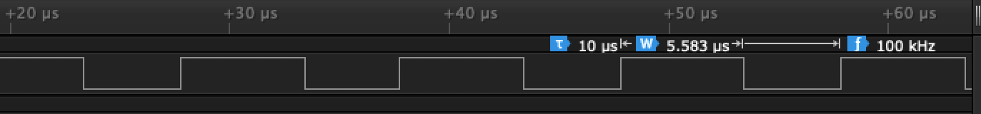
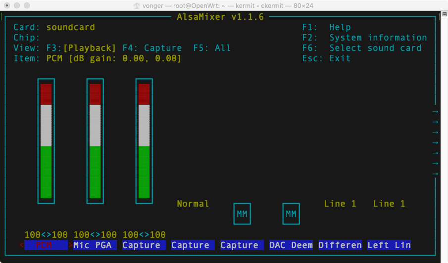
Finally it is hardware driver now, I have set i2c bus to 400KHz in VOCORE2.dts, do not waste it 🙂 Also this driver fixed i2c-mt7621 can not detect device by i2cdetect, now i2cdetect -r/-q both works well.