VoCore2: Support USB 4G LTE

I get a cheap 4G modem recently. Very interesting, my BOM cost of such thing will be over 150CNY(consider mass production 10K), but the provider of the 4G modem sell it only 100CNY and provide 6GB free data usage…

The modem is based on MDM9600 from Qualcomm which is well known since 2012.

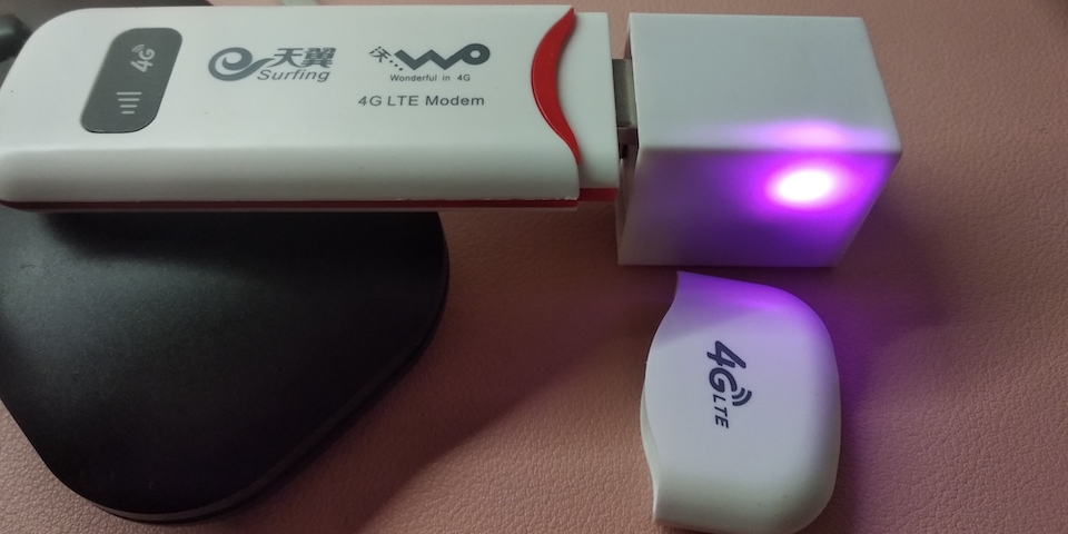
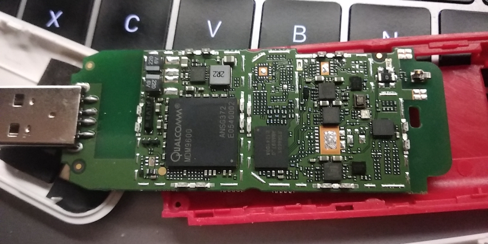
PS: now I know the low cost secret 🙂 all recycle chips…kind of environmentalist?


Let me explain how to make it work with VoCore2.

Prepare Firmware

First need to add kmod-usb-serial to firmware, old version of vocore2 firmware do not have it inside, you need to recompile your firmware and put the driver inside…it can not be install from opkg update. Or use later than 20190802 version firmware, I have embed it into firmware.

It is in make menuconfig -> Kernel modules -> USB Support -> (* or M)kmod-usb-serial

After this, we can upload the firmware to vocore2 and use opkg install other necessary packages(or you can directly compile them from source)

opkg update
opkg install usb-modeswitch usbutils

Install these packages should be enough, but in order to make it easier, we can also install luci-proto-3g, so we can setup in luci web interface.

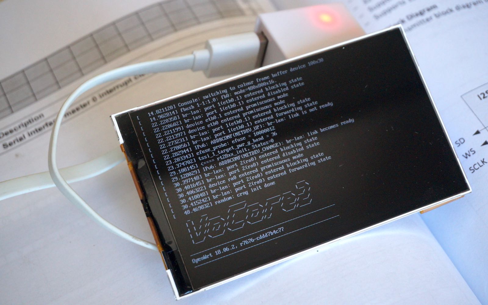
Once we plugin the USB 4G modem to vocore2 usb port, new device will show when you call lsusb:

Bus 001 Device 003: ID 05c6:92fe Qualcomm, Inc

This is not the real modem, just a virtual usb disk, we need to use usbmode to switch it into modem mode.

openwrt provided usb-modeswitch can do this, but it do not have my 4G modem USB VID/PID which is 05c6:92fe.

I have to patch /etc/usbmode.json in vocore2. add config to its line 453, right after 05c6:9024

"05c6:92fe": {                                                  
                        "*": {                                                  
                                "t_vendor": 1478,                               
                                "t_product": [ 36901 ],                         
                                "mode": "StandardEject",                        
                                "msg": [  ]                                     
                        }
             },       

PS: just eject the disk then the mode changes…simple.

and then call “usbmode -s”, the USB disk now switch to real LTE modem.

now call lsusb, you will find a new device:

Bus 001 Device 003: ID 05c6:9201 Qualcomm, Inc. Gobi Wireless Modem (QDL mode)

and in /dev/ folder, you will find ttyUSB0, ttyUSB1, ttyUSB2, ttyUSB3.

note: use command comgt -d /dev/ttyUSBx to check which ttyUSB is usable, mine is ttyUSB1

setup usbserial driver to this device:

usbserial is load at startup.

echo "usbserial vendor=0x05c6 product=0x9201" > /etc/modules.d/usb-serial

Or call insmod with parameters.

Now after reboot, it is ready to use.


Setup Network

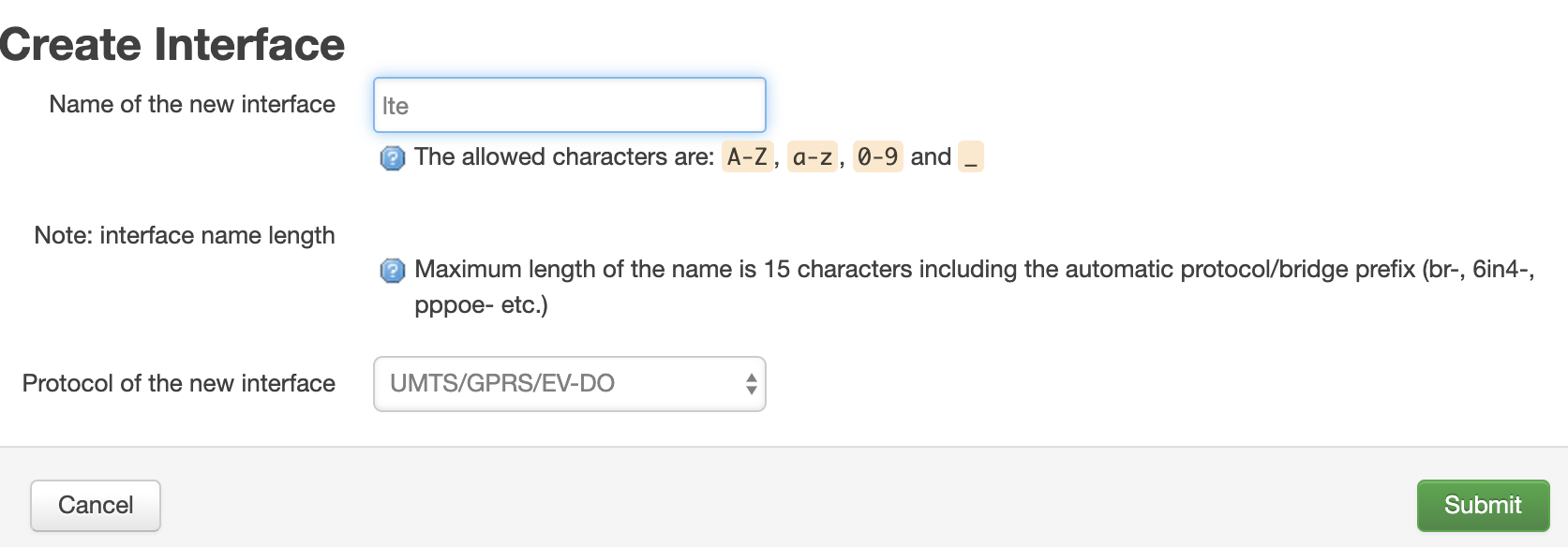
For simple, just use luci, in Network -> Interfaces, click on “Add Interface”

Then “Submit”

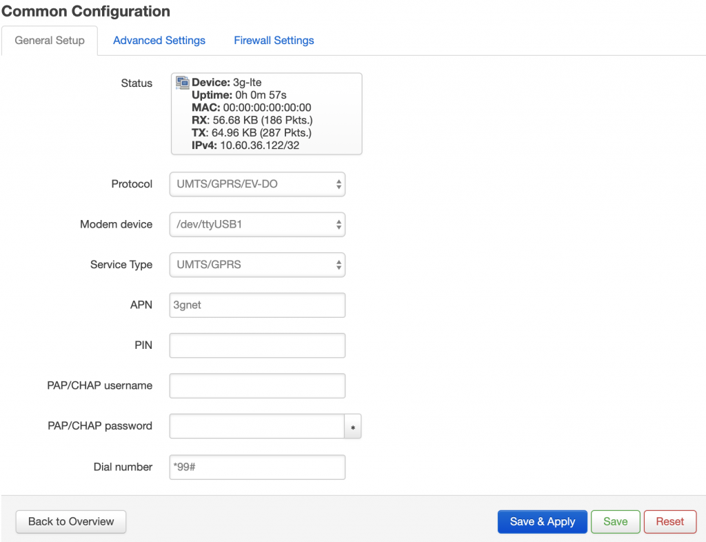
note: APN and dial number might be different for different service providers.

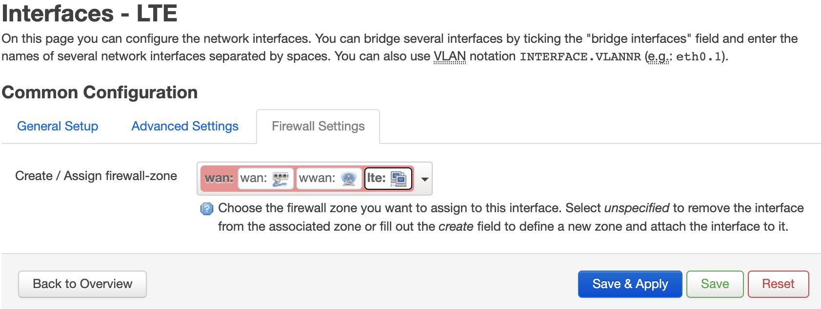
Finally, update the firewall:

Then click “Save and Apply”, you can access to internet by 4G now 🙂


Or we can do it in a HARD way, do it in console.

add config to /etc/config/network.

config interface 'lte'
   option proto '3g'
   option device '/dev/ttyUSB1'
   option service 'umts'
   option apn '3gnet'
   option dialnumber '*99#'
   option ipv6 'auto'

add config to /etc/config/firewall

config zone
	option name 'wan'
	list network 'wan'
	list network 'wan6'
	list network 'wwan'
	list network 'lte'
	option output 'ACCEPT'
	option forward 'REJECT'
	option masq '1'
	option mtu_fix '1'
	option input 'ACCEPT'

manually run to start ppp diag…(I am lazy, did not test this, might not work) or just simply call /etc/init.d/network restart

/usr/sbin/pppd nodetach ipparam lte ifname 3g-lte lcp-echo-interval 1 lcp-echo-failure 5 lcp-echo-adaptiv

after that you can find it in your ifconfig.

3g-lte Link encap:Point-to-Point Protocol
 inet addr:10.14.231.24 P-t-P:10.64.64.64 Mask:255.255.255.255
 UP POINTOPOINT RUNNING NOARP MULTICAST MTU:1500 Metric:1
 RX packets:408 errors:0 dropped:0 overruns:0 frame:0
 TX packets:474 errors:0 dropped:0 overruns:0 carrier:0
 collisions:0 txqueuelen:3
 RX bytes:148233 (144.7 KiB) TX bytes:79615 (77.7 KiB)

And now you can access internet once connect to VoCore2 hotspot.


PS: I find a bug, after reboot, pppd service will start but after around 10 seconds, it disappears. Look like some network process killed it.

Have to change the /etc/config/network, ttyUSB1 change to ttyUSB2(or USB2 to USB1) and restart network after boot up ready.

USBScreen: PT4103 issue

Currently USB screen are using two version of power supply chip, one is SY7200AABC, another is PT4103.

I thought they should be same function and work in same way…but I am wrong. PT4103 backlight is not as bright as SY7200AABC.

There is something wrong about PT4103…I set its current to 40mA, but the voltage on backlight is only 11.3V~11.5V, far from the required voltage 12.8V(3.2V x 4), but SY7200AABC works well, it is able to reach 12.5V.

First I think it is my design problem, maybe my resistors and inductors are wrong, but I tried modify the feedback resistor from 2ohm to 10ohm and change the inductor from 10uH~47uH, still no acceptable result. I find even I setup feedback resistor to 2ohm, the voltage is still lower than 11.5V.

I have no idea why PowTech’s PT4103 does not work, it should be a widely used chip but it is not as stable as SY7200AABC. Later version screen driver board I will use SY7200AABC.

VoCam264: Upgrade 2

Finally I get its documentation about XU registers, that means we can use its extend features now.
It supports OSD(the text on the picture, such as time or gps data), SEI(the data directly embed into the video stream, can be text or anything), motion detect (find bad guy), GPIO(not used) etc…

From my test, h264 at 25fps, 1080p, 14Mbps frame rate, power consume is 1.1w, not very low but much better than other h264 camera.
If for secure monitor or similar usage, at 5fps, 1080p is only 0.7watt.

PS: new demo and its source code example has upload to https://vocore.io/camera.html

Simple DEMO Usage:

1. Record 10 seconds(25fps, 250 frames) video stream into h264 file(RecordH264.h264).
note: Copy TestAP to /tmp or SD card folder, make sure the folder has at least 20MB free space.
./TestAP /dev/video1 –format H264 –size 1920×1080 –record –capture=250 –fr 25

2. Set H264 bitrate to 4Mbps.
./TestAP /dev/video1 –xuset-br 4000000

PS: its log will show XU_Multi_Get_Enable failed, ignore that, it should be something this camera do not support, once you find XU_H264_Set_BitRate <== Success, it is success.

This demo code is pretty bad but works…Later I will try to clean up the code and make a new demo.


VoCore2 Screen: Framebuffer driver port to Raspberry Pi

This is just the first step…

PS: take by crap phone camera, not screen capture, sorry about the bad image quality.

I find last time I can not insmod fbusb.ko to raspberry pi is because a stupid issue…raspberry pi already have a module named usbtest.ko, it is using same USB VID/PID. Ye, I can not afford that USB ID cost so I just use the chip CY7C680 default VID/PID, that cause the conflict and kernel taint… 🙂

Now it works…just replace the usbtest.ko in /lib/modules/4.19.50*/kernel/drivers/usb/misc/usbtest.ko with fbusb.xxxx.ko, in /lib/modules there are three usbtest.ko, not sure why there are so many of them…for simple, replace them all 🙂

Then reboot, you will find /dev/fb1, and write 16bit bmp to it, display normal.
It’s done. :p

PS: sudo FRAMEBUFFER=/dev/fb1 startx do not work..need deep dig into it.

VoCore2: I2C use hardware driver

Today I make some progress on i2c, because I want to use VoCore2 to driver a IR camera, its type is MLX90640, but i2c-gpio spends too much CPU and old hardware driver i2c-mt7621 can not get correct data.

i2c-gpio spends a lot of CPU time because it is using busy wait between every bit, so if I want to get MLX90640 at 8fps, it will need 800byte x 8bit x 8 = 51.2KHz, emm, currently i2c-gpio max speed is 250KHz, so it will take over 20% CPU…not a good choice.

i2c-mt7621 driver is using auto mode of mt7628’s i2c hardware, but that ‘auto’ mode only allow send byte one by one. (PS: what stupid auto mode…not auto at all…maybe something wrong?), it is much faster and less cpu taken than i2c-gpio mode, but between two bytes it has a big gap, around 50us, it is not acceptable by MLX90640, so if using this driver, I will never get 90640 correct data.

I have to find some new way… When I look into datasheet, I find mt7628 i2c also support a “sequence” mode which is able to send up to 8 bytes one time, and also get every byte status bit (status bit is NACK, ACK), this is perfect.

After several tries, I make it work successfully.

Here is the core part of code, raw patch uploaded to github.com/vonger/vocore2.git, replace old 0045 patch in openwrt.

static int mtk_i2c_trigger(struct mtk_i2c *i2c, u32 mode, u32 c)
{
	u32 val, reg = 0;

	val = (mode << SM0_MODE_SHIFT) | ((c - 1) << PGLEN_SHIFT) | SM0_TRI_BUSY; 
	iowrite32(val, i2c->base + REG_SM0CTL1);

	usleep_range(i2c->delay * c, i2c->delay * c + 50);
	if (mode == SM0_MODE_WRITE || mode == SM0_MODE_READ_ACK) {
		reg = ioread32(i2c->base + REG_SM0CTL1);
		val = (reg >> ACK_SHIFT) & ACK_MASK;
		if (val == 0)
			return -1;
	}
	return 0;
}

static int mtk_i2c_master_read(struct mtk_i2c *i2c, struct i2c_msg *cur)
{
	int used = 0;

	iowrite32(cur->addr * 2 + 1, i2c->base + REG_SM0D0);
	if (mtk_i2c_trigger(i2c, SM0_MODE_WRITE, 1) < 0)
		return -1;

	while (used < cur->len) {
		int size = min(cur->len - used, 8);

		if (used + size == cur->len)	/* last page, send NAK */
			mtk_i2c_trigger(i2c, SM0_MODE_READ_NACK, size);
		else
			mtk_i2c_trigger(i2c, SM0_MODE_READ_ACK, size);

		memcpy(cur->buf + used, i2c->base + REG_SM0D0, size);
		used += size;
	}
	return used;
}

static int mtk_i2c_master_write(struct mtk_i2c *i2c, struct i2c_msg *cur)
{
	int used = 0;

	iowrite32(cur->addr * 2, i2c->base + REG_SM0D0);
	if (mtk_i2c_trigger(i2c, SM0_MODE_WRITE, 1) < 0)
		return -1;

	while (used < cur->len) {
		int size = min(cur->len - used, 8);
		memcpy(i2c->base + REG_SM0D0, cur->buf + used, size);
		mtk_i2c_trigger(i2c, SM0_MODE_WRITE, size);
		used += size;
	}
	return used;
}

static int mtk_i2c_master_xfer(struct i2c_adapter *a, struct i2c_msg *m, int c)
{
	struct mtk_i2c *i2c = i2c_get_adapdata(a);
	int i;

	for (i = 0; i < c; i++) { 
		if (m[i].flags & I2C_M_TEN) 
			return -EINVAL; 
		mtk_i2c_trigger(i2c, SM0_MODE_START, 1); 
		if ((m + i)->flags & I2C_M_RD) {
			if (mtk_i2c_master_read(i2c, m + i) < 0)
				break;
		} else {
			if (mtk_i2c_master_write(i2c, m + i) < 0)
				break;
		}
	}
	mtk_i2c_trigger(i2c, SM0_MODE_STOP, 1);

	/* can not access one or more address in the i2c_msg */
	if (i != c)
		return -ENODEV;

	/* the return value is number of executed messages */
	return i;
}

Finally it is hardware driver now, I have set i2c bus to 400KHz in VOCORE2.dts, do not waste it 🙂 Also this driver fixed i2c-mt7621 can not detect device by i2cdetect, now i2cdetect -r/-q both works well.

VoCam264: Get H264 Data

Because of Linux kernel updated pretty fast, the demo in VoCam264 SDK is already out of date…

We will need some changes to make TestAP able to compile:

  1. change include file from <linux/videodev.h> to <linux/videodev2.h>
  2. add header include to <string.h> and <stdio.h> to sonix_xu_ctrls.c, so compiler will stop complain the missing headers.

Now we can use mipsel-openwrt-linux-gcc to compile the TestAP.

mipsel-openwrt-linux-gcc *.c -o TestAP

To record h264 data, first go to /tmp folder or /mnt/mmcblk0p1 or /mnt/sda1(make sure the device has enough space for data) then use SONiX_UVC_TestAP -c -f H264 -r /dev/video1 -s 1920×1080 record it to that folder.

It will generate a file named RecordH264.h264, you can use ffplay to watch it.

The test application will record video with bitrate around 10Mb/s, so one second it will take around 1.3MB disk space, very big 🙂 we need to find a way to reduce the bitrate. I guess that will have to use its XU interface, but because Linux UVC interface changed, we do not have UVCIOC_CTRL_ADD, UVCIOC_CTRL_SET and UVCIOC_CTRL_GET anymore, the demo code is totally broken now, have to upgrade and patch it..

Now new interface is UVCIOC_CTRL_MAP which used to replace UVCIOC_CTRL_ADD and UVCIOC_CTRL_QUERY, which used to replace UVCIOC_CTRL_SET/GET.

Such as OSD function and motion detection function are both depends on those XU functions.

To be continue…❤️

VoCore2: Interesting issue of UART

I find a weird issue, if I use one VoCore2 UART0 to read another VoCore2 UART2(debug output), I will get some random chars at uboot output stage, then once Linux load UART driver, the output become normal.

Finally I find out the problem, this is because uboot serial port baudrate is not correct…

From MT7628 datasheet, if we want set serial port to 115200Hz, we should set register to 2500000 / 115200Hz = 21.7, but the register only accept integer…in uboot code, it sets register to 21, but in Linux driver code, set it to 22, you see that is a very big difference. In uboot, the real frequency is 2500000 / 21 = 119007Hz, but in Linux, it is 2500000 / 22 = 113636Hz. This difference make the UART can not decode the wave correctly then cause it display the random chars.

Interesting thing is, CP2102 and GD32F150 both do not have such issue. They must using some other way to decode the UART wave, so it can ignore the big gap 🙂

I have updated uboot code(set register to 22, same as Linux UART driver) and uploaded to vocore.io/v2.html download zone, please update and have a try 🙂

To upgrade uboot, in uboot menu, choose ‘7’, then use kermit protocol upload the uboot, rest uboot will do it automatically.

VoCore2: PWM control motor

VoCore2 has four PWM port, so with GPIOs, we can drive up to four motors or two stepper motors.

The picture shows the four ports.

To use PWM2, PWM3, we need switch this pin group from “uart2” to “pwm”, I have added this to github vocore2 patch.

PS: I use uart2 as console port, but not this group, so no conflict. This group named “uart2” but my real UART2 is using group “spis”, this is defined in Linux kernel source in arch folder, search mt7620.c

And we also need necessary driver for pwm port, openwrt already have it. We just need to select it from openwrt menuconfig => Kernel modules => Other modules => kmod-pwm-mediatek-ramips.

Now everything require for firmware is ready. Latest firmware (>20190624) already have pwm support.

Now we can try PWM, for example, I use PWM3 as output.

echo 3 > /sys/devices/platform/10000000.palmbus/10005000.pwm/pwm/pwmchip0/export

now in

/sys/devices/platform/10000000.palmbus/10005000.pwm/pwm/pwmchip0/, you will find a new folder named “pwm3”, in it, there are some files.

root@OpenWrt:/sys/devices/platform/10000000.palmbus/10005000.pwm/pwm/pwmchip0/pwm3# ls
capture     duty_cycle  enable      period      polarity    uevent

‘duty_cycle’ is how much high in one period, and ‘period’ is the time of one period, from my test, period unit is 1ns. and its value range is 10000~100000(10K~100KHz), ‘enable’ is use to enable PWM output, these three interface are enough to control simple PWM wave.

Let’s try:

echo 10000 > period
echo 5600 > duty_cycle
echo 1 > enable

From my logic analyzer, it has pretty good result:

PS: its output is exactly 5.6us, just this analyzer do not good enough to show that. 🙂


To be continue…

VoCam264: Upgrade

VoCam264 now has a new upgrade.

  1. removed the power noise on CMOS.
  2. reduce the hot noise on CMOS.
  3. reduce around 100mW power usage.
  4. new design make it easy to adjust lens.
  5. better thermal design, no heatsink.
  6. in 40C environment, still have good quality video.
  7. small size, compare to old version, 3mm more in width.

From my test, at 29.5C environment, power consume is around 800mW, camera temperature is around 49C at 1080p 25fps.

I am pretty happy to this result. 🙂

Compare to Macbook Pro Facetime camera in dark environment.

The upper one is captured by facetime camera…

This one is captured by VoCam264.

I know both of them are very dark(maybe need an eagle eye :), we can clearly find out, VoCam264 is much lower noise and more details in a dark area.

PS: now 800w camera is already come, but from my test, its power consume is very high, also need more power to transfer the data…my production target is small, low power consume and most important, price should keep low. 1080p is already good enough for most usage, so I will keep current solution for one or two more years.