Recently Wuhan Virus is pretty bad in China, hopefully everything back well soon.
Now I have success use GPIO as CS pins, it is not hard but have to cost a lot of time understanding how the SPI driver works 🙂
Here is the patch for spi-mt7621.c, also upload to github.com/vonger/vocore2, 811-spi-gpio-chip-select.patch
 --- a/drivers/spi/spi-mt7621.c
 +++ b/drivers/spi/spi-mt7621.c
 @@ -107,9 +107,15 @@
      u32 polar = 0;

      mt7621_spi_reset(rs, cs);
 +
 +    if (cs >= 2) { /* gpio chip select mode */
 +        enable = (spi->mode & SPI_CS_HIGH) ? enable : !enable;
 +        gpio_set_value_cansleep(spi->cs_gpio, enable);
 +    } else {
           if (enable)
               polar = BIT(cs);
           mt7621_spi_write(rs, MT7621_SPI_POLAR, polar);
 +    }
  }

  static int mt7621_spi_prepare(struct spi_device *spi, unsigned int speed)
 @@ -383,9 +389,17 @@
   return -EINVAL;
   }

 +     if (spi->chip_select >= 2 && gpio_is_valid(spi->cs_gpio))
 +         gpio_request_one(spi->cs_gpio, GPIOF_OUT_INIT_HIGH, dev_name(&spi->dev));
 +
   return 0;
  }

 +static void mt7621_spi_cleanup(struct spi_device *spi)
 +{
 +     gpio_free(spi->cs_gpio);
 +}
 +
  static const struct of_device_id mt7621_spi_match[] = {
   { .compatible = "ralink,mt7621-spi" },
   {},
 @@ -438,10 +452,11 @@
   master->mode_bits = RT2880_SPI_MODE_BITS;

   master->setup = mt7621_spi_setup;
 + master->cleanup = mt7621_spi_cleanup;
   master->transfer_one_message = mt7621_spi_transfer_one_message;
   master->bits_per_word_mask = SPI_BPW_MASK(8);
   master->dev.of_node = pdev->dev.of_node;
 - master->num_chipselect = 2;
 + master->num_chipselect = of_gpio_named_count(pdev->dev.of_node, "cs-gpios");
   master->max_transfer_size = mt7621_max_transfer_size;

   dev_set_drvdata(&pdev->dev, master);
Here is the patch explain:
- For chip select number is 0,1, we use old driver way, SPI hardware register will control the CS0 and CS1
- For the chip select we added, CS2, CS3, etc, we use GPIO way, so we call gpio_set_value_cansleep, use GPIO way to control them.
- In order to use those GPIO, we need to call gpio_request to alloc GPIO from the kernel, once it is done, we use gpio_free to release resource.
- SPI master max SPI device now is not 2, it is the GPIO CS pins we defined in DTS(device tree file)
After this patch, we have the SPI new driver ready, but still need to setup DTS to tell the driver which GPIO we want to use as CS pins.
 &spi0 {
     status = "okay";

     cs-gpios = <&gpio0 6 GPIO_ACTIVE_HIGH>,
                <&gpio0 10 GPIO_ACTIVE_HIGH>,
                <&gpio1 5 GPIO_ACTIVE_HIGH>,
                <&gpio1 6 GPIO_ACTIVE_HIGH>;


     m25p80@0 {
         ...
     };

     spidev1@1 {
         #address-cells = <1>;
         #size-cells = <1>;
         compatible = "rohm,dh2228fv";
         reg = <1>;
         spi-max-frequency = <100000000>;
     };

     spidev2@2 {
         #address-cells = <1>;
         #size-cells = <1>;
         compatible = "rohm,dh2228fv";
         reg = <2>;
         spi-max-frequency = <100000000>;
     };

     spidev3@3 {
         #address-cells = <1>;
         #size-cells = <1>;
         compatible = "rohm,dh2228fv";
         reg = <3>;
         spi-max-frequency = <100000000>;
     };
};
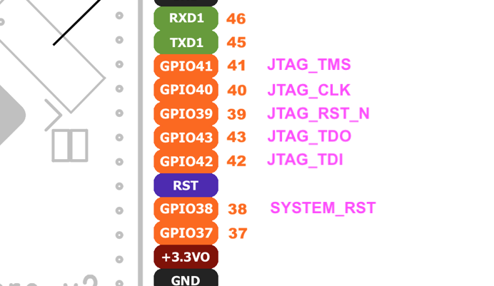
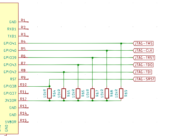
<GPIO0 5> <GPIO0 10> is not really used as GPIO, just a place holder for CS0, CS1. <GPIO1 5> is CS2, it is GPIO37(32+5), <GPIO1 6> is CS3, it is GPIO38(32+6). Once we have this, we can connect SPI device CS pins to it, I use spidev_test check if it is working.
Note: spi-mt7621 max allowed data length is 16byte, so do not send data exceeds this number, or it will oops. Use ‘-p’ parameter to avoid spidev_test default send 38 bytes.
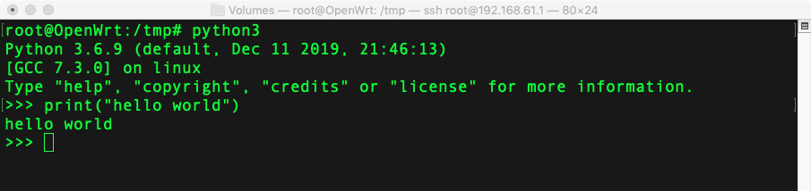
My test result:
root@OpenWrt:/# spidev_test -D /dev/spidev0.3 -p '\x020'
spi mode: 0x0
bits per word: 8
max speed: 500000 Hz (500 KHz)
RX | 00 1A __ __ __ __ __ __ __ __ __ __ __ __ __ __ __ __ __ __ __ __ __ __ __ __ __ __ __ __ __ __  | ..
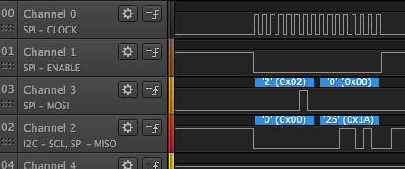
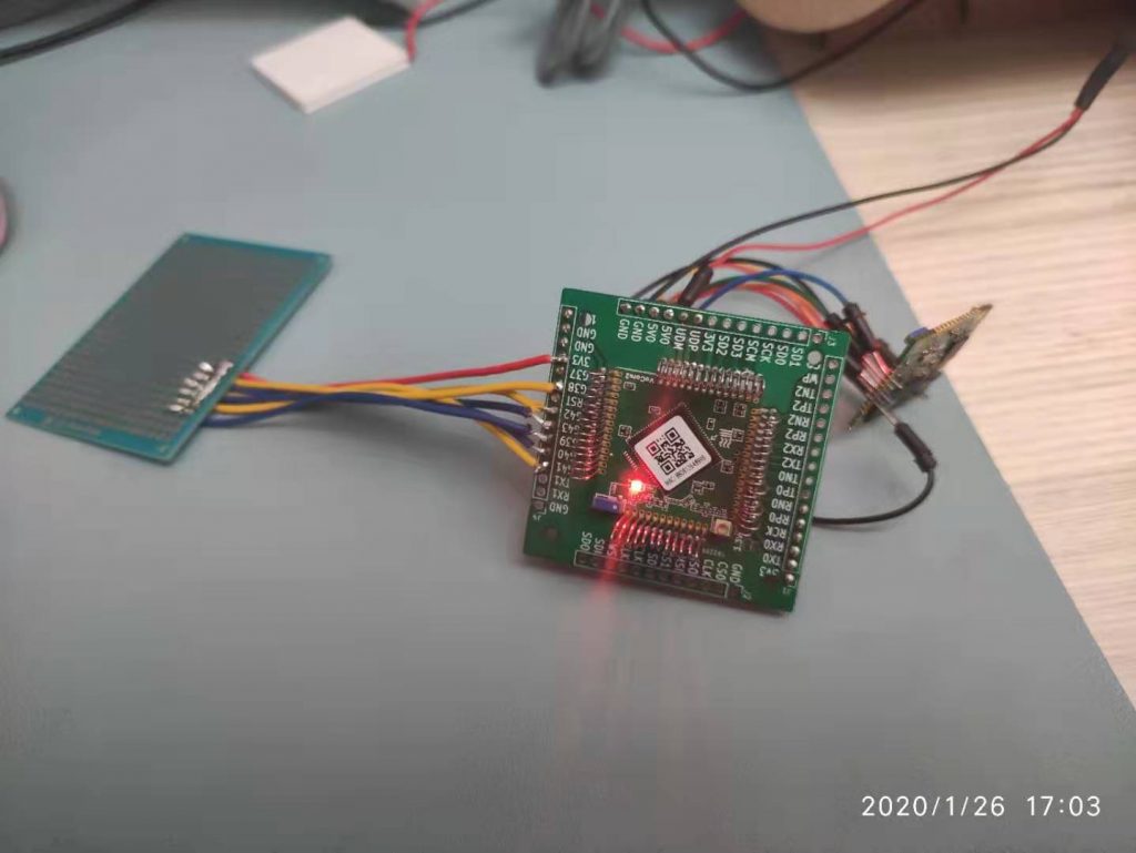
I connected one LoRA device SX1278, and using spidev0.3, in DTS it is spidev3@3, I can successfully read its 0x02 register and get its data is 0x1A.
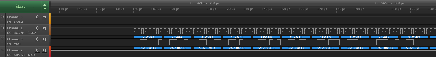
Here is the same data I read from logic analyzer.