But my computer is able to connect to it!
Miracle!!
In fact, even I did not connect any antenna to the board but there is a very very short “antenna” on board. And my computer is just 1m from that board. Then, it connected. LOL 😀
But my computer is able to connect to it!
Miracle!!
In fact, even I did not connect any antenna to the board but there is a very very short “antenna” on board. And my computer is just 1m from that board. Then, it connected. LOL 😀
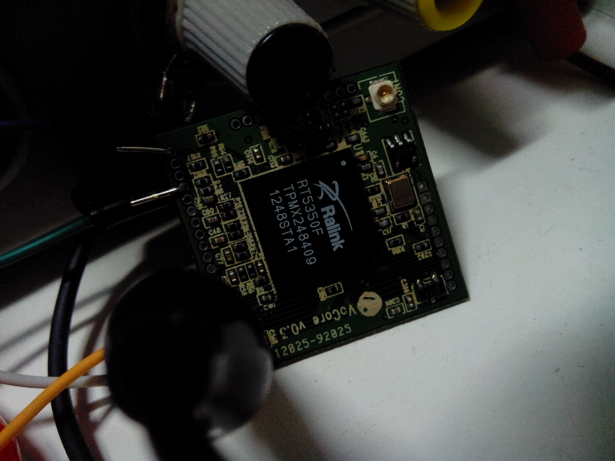
Today I use a infrared thermometer on the RT5350F chip, the temperature is 68~70°C…
On the datasheet its working temperature is -10°C~55°C…
How is this possible? I did not run my customised application yet. T-T
Another good day!
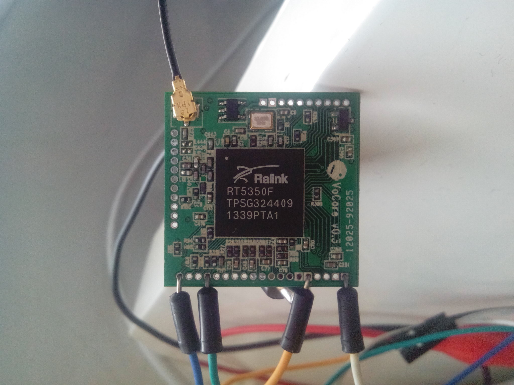
I can not wait for the new 2.2nH and 2.7nH from chip reseller. So I just get two 2.7nH from my old board then solid it onto VoCore v0.3, now it works. Fantastic!
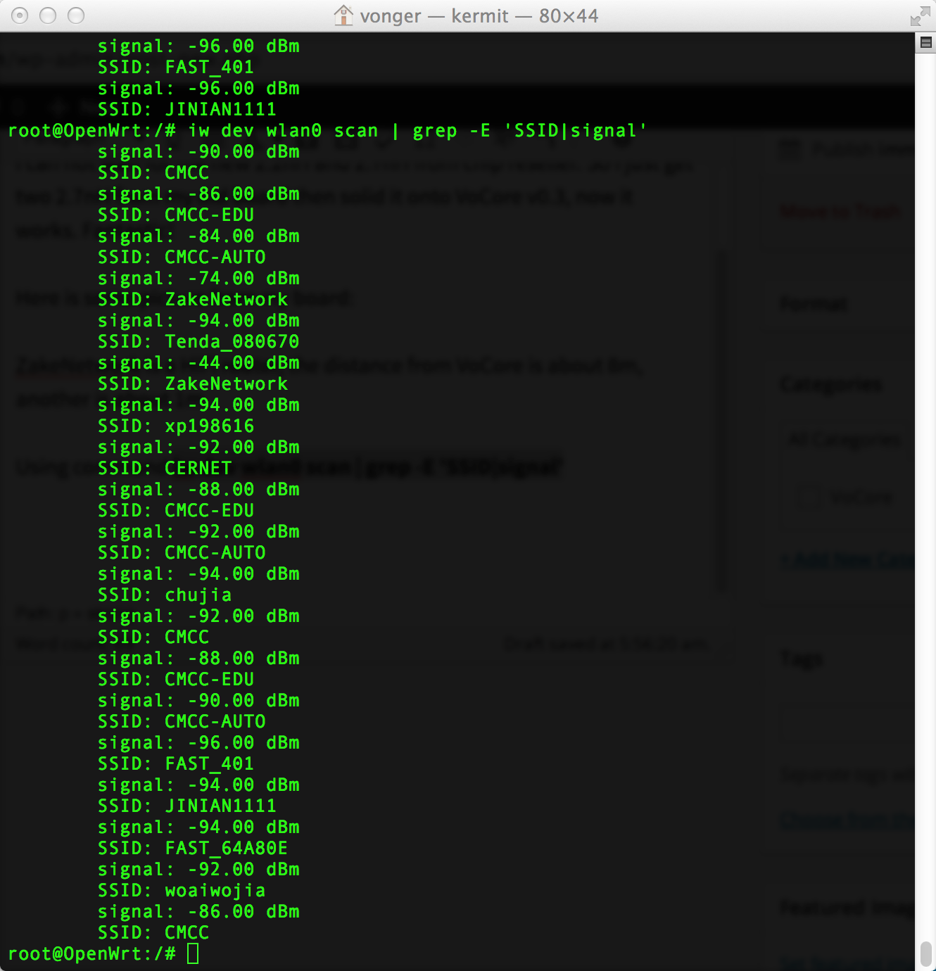
Here are some screen captures from my board:
ZakeNetwork is a HiFi router, the distance from VoCore is about 8m(-70dBm), another is about 1m(-40dBm).
Using command iw dev wlan0 scan | grep -E ‘SSID|signal’
Pictures from the new wifi valid VoCore v0.3. 🙂
  PID USER       VSZ STAT COMMAND
    1 root      1344 S    /sbin/procd
    2 root         0 SW   [kthreadd]
    3 root         0 SW   [ksoftirqd/0]
    4 root         0 SW   [kworker/0:0]
    5 root         0 SW<  [kworker/0:0H]
    6 root         0 SW   [kworker/u2:0]
    7 root         0 SW<  [khelper]
    8 root         0 SW   [kworker/u2:1]
   63 root         0 SW<  [writeback]
   65 root         0 SW<  [bioset]
   67 root         0 SW<  [kblockd]
   90 root         0 SW   [kworker/0:1]
   96 root         0 SW   [kswapd0]
  141 root         0 SW   [fsnotify_mark]
  165 root         0 SW   [spi32766]
  205 root         0 SW<  [deferwq]
  256 root         0 SW   [khubd]
  331 root       884 S    /sbin/ubusd
  332 root      1496 S    /bin/ash --login
  413 root         0 SW<  [cfg80211]
  562 root      1312 S    /sbin/logd
  575 root      1512 S    /sbin/netifd
  616 root      1488 S    /usr/sbin/telnetd -F -l /bin/login.sh
  654 nobody     964 S    /usr/sbin/dnsmasq -C /var/etc/dnsmasq.conf -k
  734 root      1496 S    udhcpc -p /var/run/udhcpc-eth0.2.pid -s /lib/netifd/dhcp.script -f -t 0 -i eth0.2 -C
  760 root         0 SWN  [jffs2_gcd_mtd5]
  792 root      1160 S    /usr/sbin/dropbear -F -P /var/run/dropbear.1.pid -p 22
  797 root      1496 S    /usr/sbin/ntpd -n -p 0.openwrt.pool.ntp.org 1.openwrt.pool.ntp.org 2.openwrt.pool.ntp.org 3.openwrt.pool.
Filesystem           1K-blocks      Used Available Use% Mounted on
rootfs                    5184       268      4916   5% /
/dev/root                 1792      1792         0 100% /rom
tmpfs                    14788        44     14744   0% /tmp
tmpfs                    14788         8     14780   0% /tmp/root
tmpfs                      512         0       512   0% /dev
/dev/mtdblock5            5184       268      4916   5% /overlay
overlayfs:/overlay        5184       268      4916   5% /
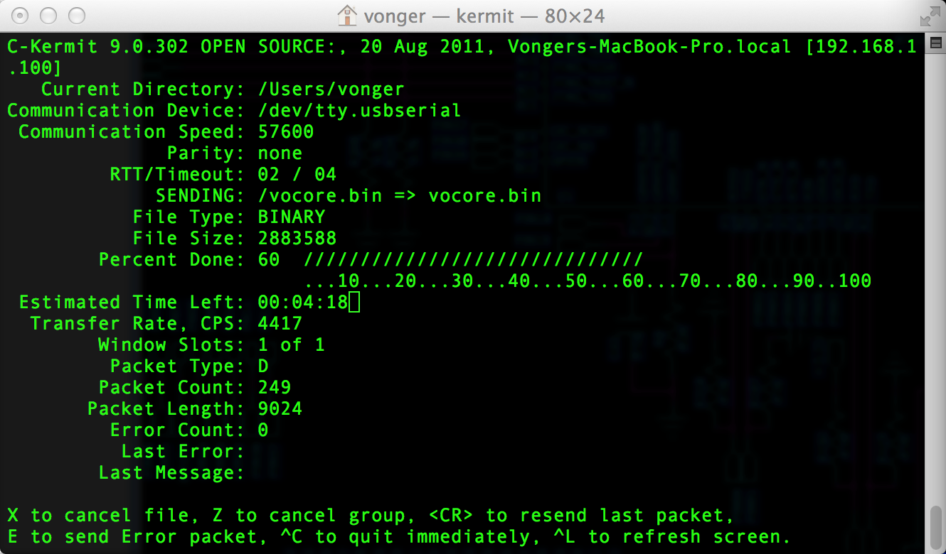
vocore.bin size 2883588(0x2c0004) => download here. In bootloader, use loadb command to transfer it from local to vocore memory. Then call cp.linux 2c0004 to copy it to flash. If there already exists old linux, call erase linux to delete old one.
The offical bootloader loadb command might not working. We have to change some code on its uboot. Details here: https://forum.openwrt.org/viewtopic.php?id=44472
VoCore v0.3 solid is done 🙂 Here is the picture.
不再有飞线的和平世界 ^_^
It is night, a little dark.
I am lucky, the first time I connect it to 3.3V, success into boot loader and linux system.
Bad news is wifi do not work at all.
Good news is I just find the problem in two minutes. There are two inductance on the antenna, one should be 2.2nH and another should be 2.7nH, but the real one I solid onto the board is 2.2uH and 2.7uH…Thousand times bigger than my schematic value. The careless seller send me the wrong inductance. I have to wait them send the right one and test wifi part later.
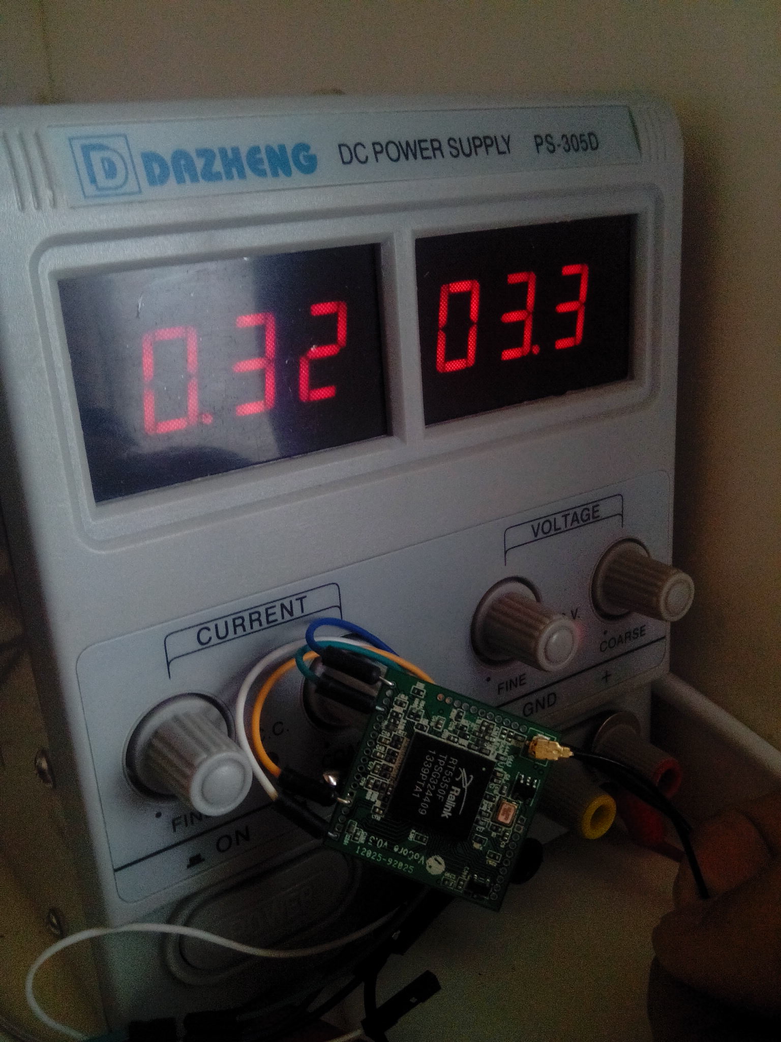
3.3V/0.3A = 1W: run linux with wifi on/ethernet on(two ports).
3.3V/0.25A = 0.825W: run linux with wifi on.
3.3V/0.15A = 0.495W: run linux with wifi off.
Finally VoCore v0.3 PCB comes to my home today. Now there is no jump wire anymore.
So happy, now I have a board that I have full control on it.
I have a raspberrypi, I can not full control it and I have to buy a 30USD camera, that is expensive. I want to DIY one, but camera interface is not opened. I really hate that, I just want to control every corner of my own board. That is one important motivation for me to make VoCore. I think if you want every one to use it for study or learn programming, it is better to open them all.
But for my module, in my further plan, I will make a camera based on OV2640 or OV3660 which supply JPEG format output, the camera price will be under 10USD.
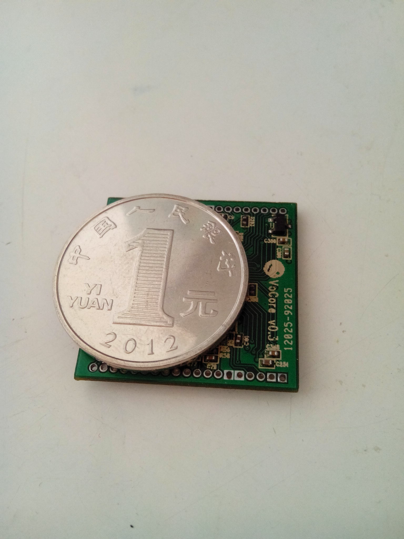
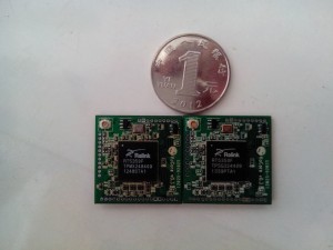
Next version should be the final version, v0.4, in that version I will use “Semi-hole technology”(searched from google, in Chinese it should be 半孔工艺) to make the board smaller. Now its size is 27mm x 27mm, a little bigger than 1RMB coin(25mm). Next version it will be 24mm x 25mm with a on board Ceramic Antenna, but I am not sure about that, I need to test on 0.3 first to make sure ceramic antenna works well on my side.
After wifi test/GPIO test and other test is done from my side, I will make about 100p, and try to sell it at 10USD on taobao/ebay. Hopefully then more people will help me develop it and make this one better or even smaller. Software and hardware will be all open forever. 🙂
This module, in some situation, it is better than arduino for study embed.
From my search online, now I am sure, VoCore0.3 is the SMALLEST/CHEAPEST/28GPIO&other interface Linux Router Module in the World 🙂
The price should be less than 10USD. But it can do job as a full function linux MIPS computer with wifi.
在网上搜了半天,现在我可以确定,VoCore v0.3是世界上最小的最便宜的,28个GPIO及其他的各种接口最全的Linux路由器模块。
批量生产价格应该在60元人民币以下,但是它其实就是一台带wifi的linux小电脑。
The following two files are used for personal study. If you want to use it in commerce area, please contact vonger@live.com.
以下的文件只可用于个人学习和研究。如果您需要用于商业用途,请邮件联系vonger@live.com,适量收取一些开发测试费用,如果有定制开发需求,也可和我联系。
PCB files:(PDF format)
SCH files:(PDF format)
Waiting for new 0.3 PCB from factory…It is a long time…
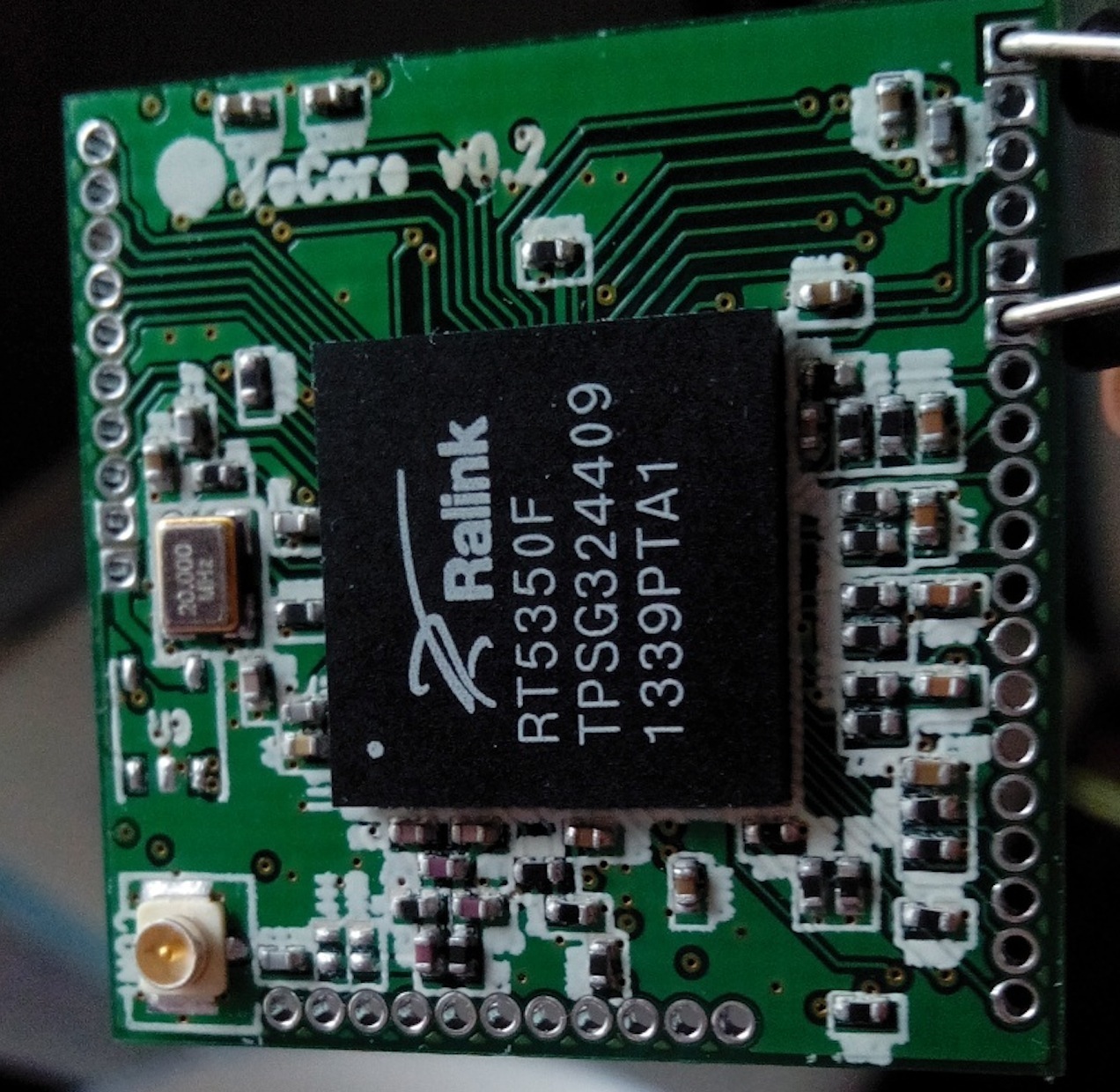
So I decide to complete that “jump wire” VoCore v0.2. After several attempts, it works now!
This are some screen captures 🙂
Downloading openwrt to my VoCore by UART Lite.
Run top on board.

I am a real newbie on hardware 🙂
VoCore 0.2 has failed, when I connect it to power, some time the current cost is 0.20A but some time the current cost is 0.23A and RXD2/TXD2 is always high, it should change to low once the chip on boot process. So I guess the problem is before bootstrap, and the problem might be I floated PORST_N which is used to reset the chip.
For v0.2, I just simply followed the datasheet of RT5350F and trust its “internal pull up”. But in fact, reset can not work that easy way. it will be pull high once it connect to 3.3V then it will be pull low for a few ms(140ms~400ms), so if I just pull it to high will cause problem.
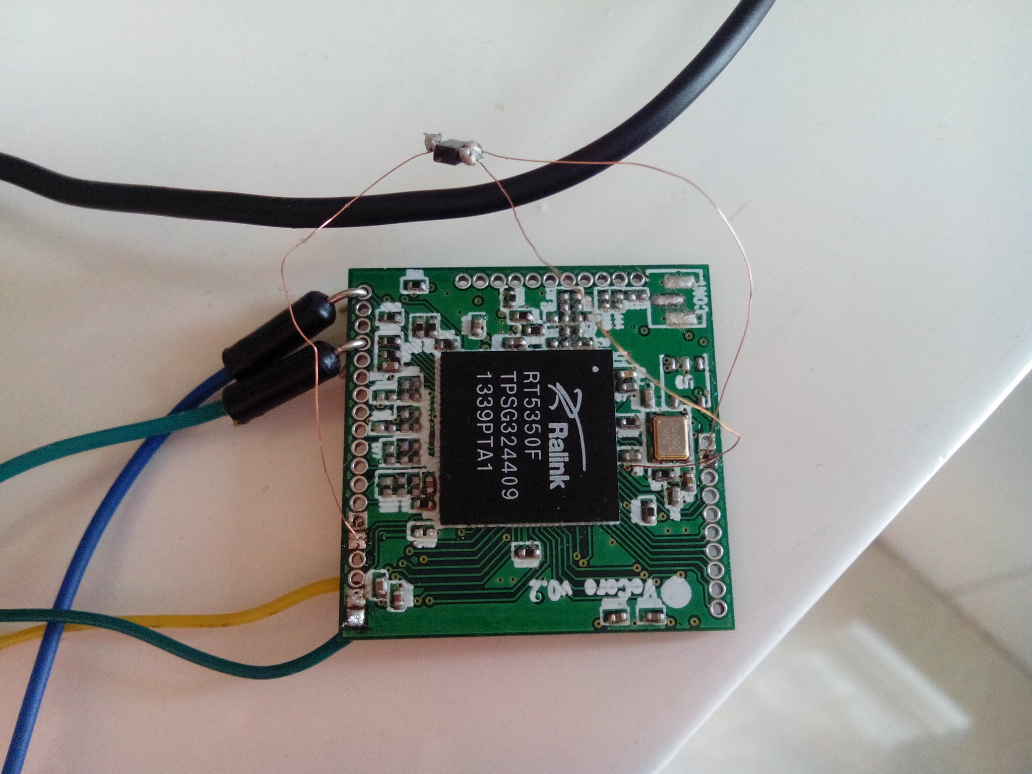
OK, then I jump a wire under BGA as following. Plan to connect a chip named MAX809S, it is a reset circuit. It is used to make reset stable.

Then solid all parts on. Then do a few test…
Connect to power, now it current consume is fixed to 0.20A, not float between 0.20A ~ 0.23A anymore. So I think at least the reset part is normal now.
Connect with TXD2 to a PL2302 USB-TTL device, I find TXD2 changed to low after boot, so boot strap is normal.
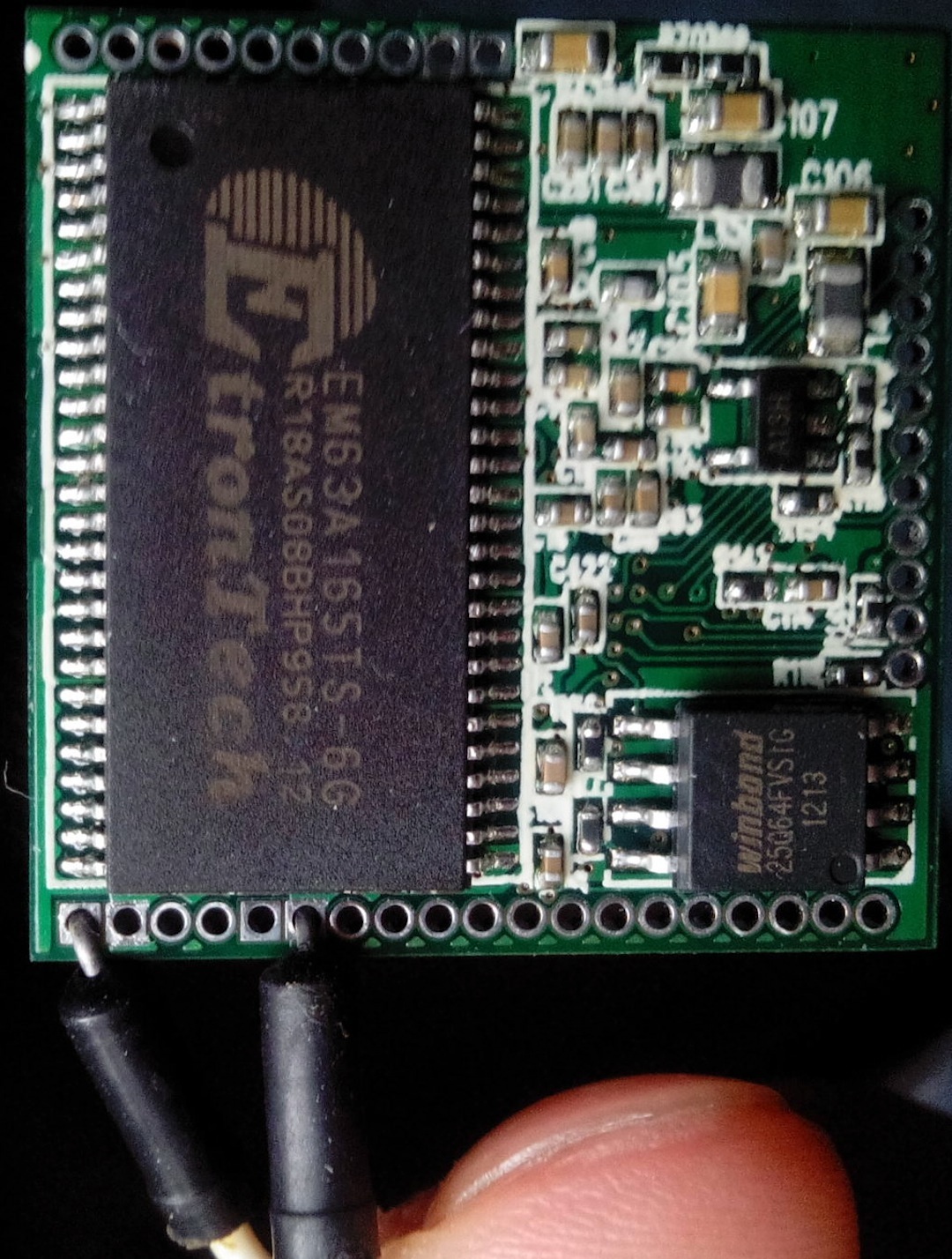
Then I try to read from the chip, no luck, nothing output. I tried many times, but no success. Only one time it output some REAL char when I press the memory hard onto the board(I am so happy when I get that output, it is close to success). I think there must be something wrong on the memory. Then I use ohmmeter to check between memory solid pad and memory chip foot, find at least 5 feet are not really connected to the pad. For fix that, I tried to use the high skill called “drag-soldering”, but just make my board into mess… and I lose one memory chip. 🙂
Another try is to solid another board, but this time BGA has some problem because of the jump wire. I have to stop here, or I will lose more RT5350F. :'(
For next step, I’d better to make another board, then use the “print-solid” way, much easier for a newbie and that will have high rate to success.
Show my current work.