Category Archives: VoCore

VoCore2: wifi driver mt76 vs mtwifi

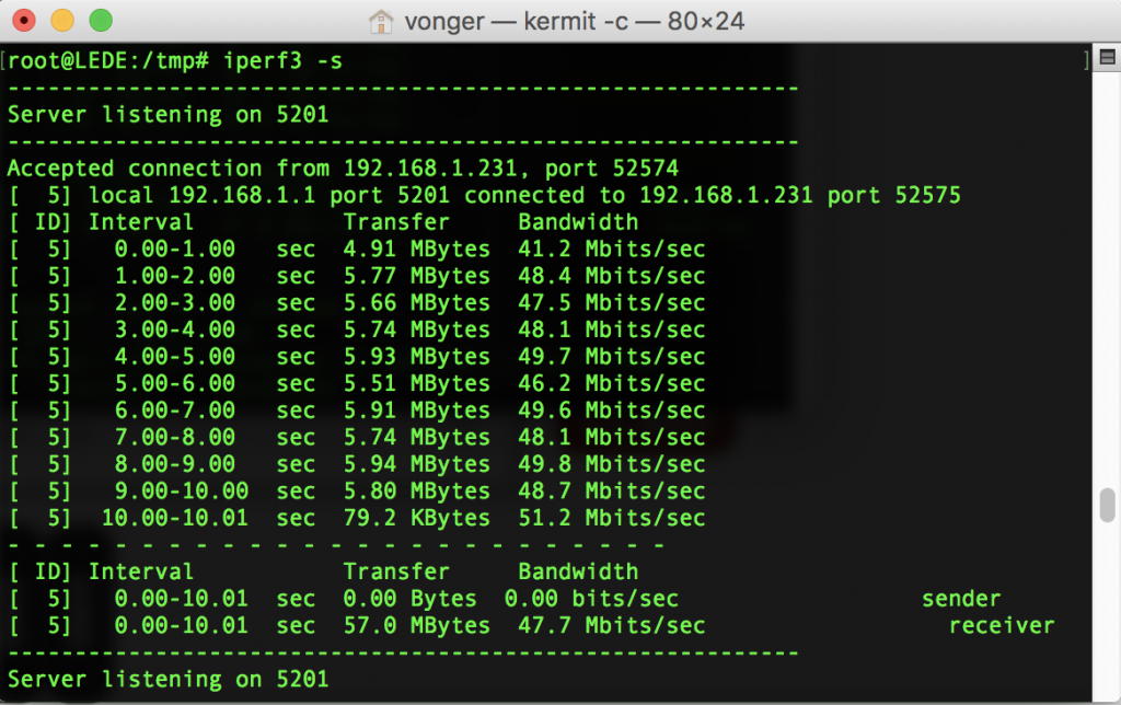
Use iperf3 test same VoCore2, enable one antenna.

official driver from mediatek:

[ 4] 0.00-1.00 sec 5.46 MBytes 45.8 Mbits/sec
[ 4] 1.00-2.00 sec 5.71 MBytes 47.8 Mbits/sec
[ 4] 2.00-3.00 sec 5.51 MBytes 46.2 Mbits/sec
[ 4] 3.00-4.00 sec 5.24 MBytes 44.0 Mbits/sec
[ 4] 4.00-5.00 sec 5.60 MBytes 47.0 Mbits/sec
[ 4] 5.00-6.00 sec 5.61 MBytes 47.0 Mbits/sec
[ 4] 6.00-7.00 sec 5.64 MBytes 47.3 Mbits/sec
[ 4] 7.00-8.00 sec 5.34 MBytes 44.8 Mbits/sec
[ 4] 8.00-9.00 sec 5.39 MBytes 45.2 Mbits/sec
[ 4] 9.00-10.00 sec 5.34 MBytes 44.8 Mbits/sec
- - - - - - - - - - - - - - - - - - - - - - - - -
[ ID] Interval Transfer Bandwidth
[ 4] 0.00-10.00 sec 54.8 MBytes 46.0 Mbits/sec sender
[ 4] 0.00-10.00 sec 54.8 MBytes 45.9 Mbits/sec receiver


mt76 driver from LEDE/openwrt(https://github.com/openwrt/mt76):

[ 4] 0.00-1.00 sec 2.29 MBytes 19.2 Mbits/sec
[ 4] 1.00-2.00 sec 2.28 MBytes 19.1 Mbits/sec
[ 4] 2.00-3.00 sec 3.57 MBytes 29.8 Mbits/sec
[ 4] 3.00-4.00 sec 2.98 MBytes 25.1 Mbits/sec
[ 4] 4.00-5.00 sec 4.98 MBytes 41.8 Mbits/sec
[ 4] 5.00-6.00 sec 2.68 MBytes 22.5 Mbits/sec
[ 4] 6.00-7.00 sec 4.21 MBytes 35.4 Mbits/sec
[ 4] 7.00-8.00 sec 3.79 MBytes 31.8 Mbits/sec
[ 4] 8.00-9.00 sec 4.55 MBytes 38.1 Mbits/sec
[ 4] 9.00-10.00 sec 2.79 MBytes 23.5 Mbits/sec
- - - - - - - - - - - - - - - - - - - - - - - - -
[ ID] Interval Transfer Bandwidth
[ 4] 0.00-10.00 sec 34.1 MBytes 28.6 Mbits/sec sender
[ 4] 0.00-10.00 sec 33.4 MBytes 28.1 Mbits/sec receiver

mt76 driver is not very stable, and speed is only 60% of official driver. 🙂 So there is something I can help to improve.

VoCore2: Connect to SPI Screen 2

I am lucky, the screen backlight is not damaged by my mistake. 😂

1. connect the super tiny driver board to the screen.


2. power it up with 3.3V.

The LCD backlight power consume is 5V 100mA, 0.5w, pretty much. I think that’s why the media always says the screen is one of the most power-hungry components in the phone. 😅

Next part, let’s hack SPI and check if we can display anything to it.

PS: many people(include me) find white VoCore2 is hard to clean and go ugly after solder wires, so if no special request, we will ship green pcb version at vocore.io/store(also we still product white pcb version).

VoCore2: Its time to LEDE

Thanks to all LEDE contributors, I just find current LEDE is very fast and stable, I think it is the time to merge all drivers to LEDE 🙂

New LEDE firmware is here: https://downloads.lede-project.org/snapshots/targets/ramips/mt7628/lede-ramips-mt7628-vocore2-squashfs-sysupgrade.bin

Note: make sure you have a USB2TTL, its wifi is default off, as I know that is for secure reason?

Same as usual, I will also share my advanture on this blog.

VoCore2: Fix microSD randomly umount issue

The day before yesterday I released a firmware fixed the microSD randomly umount issue. Now let me explain how it works. (Lastest Firmware: Link)

People report this issue: they find the following log in console when they trying to using microSD.

[ 112.750000] msdc-1 -> cmd card power PID<kworker/u2:1>
[ 112.750000] msdc-1 -> cmd card power PID<kworker/u2:1>
[ 112.760000] msdc-1 -> cmd card power PID<kworker/u2:1>
[ 112.770000] msdc-1 -> cmd card power PID<kworker/u2:1>
[ 112.780000] mmc0: card aaaa removed
[ 112.800000] EXT4-fs error (device mmcblk0p1): ext4_wait_block_bitmap:494: comm kworker/u2:3: Cannot read block bitmap - block_group = 0, block_bitmap = 475
[ 112.820000] EXT4-fs warning (device mmcblk0p1): ext4_end_bio:317: I/O error -5 writing to inode 12 (offset 0 size 4194304 starting block 34175)
[ 112.820000] Buffer I/O error on device mmcblk0p1, logical block 33792
[ 112.820000] Buffer I/O error on device mmcblk0p1, logical block 33793
[ 112.820000] Buffer I/O error on device mmcblk0p1, logical block 33794
[ 112.820000] Buffer I/O error on device mmcblk0p1, logical block 33795
[ 112.820000] Buffer I/O error on device mmcblk0p1, logical block 33796

microSD is umount randomly and microSD card can not use at all.

After some research, I find it is caused by microSD driver. VoCore2 do not have CD(card detect pin), but driver use that pin for card detect, even we already set “cd-poll” and “broken-cd” in VOCORE2.dts, but looks like the mmc driver did not code such flag.

I have to make a patch to fix it.


--- a/drivers/mmc/host/mtk-mmc/sd.c
+++ b/drivers/mmc/host/mtk-mmc/sd.c
@@ -580,6 +580,7 @@
inserted = (status & MSDC_PS_CDSTS) ? 0 : 1;
else
inserted = (status & MSDC_PS_CDSTS) ? 1 : 0;
+ inserted = 1;
}

#if 0
@@ -2328,6 +2329,7 @@
present = (sdr_read32(MSDC_PS) & MSDC_PS_CDSTS) ? 0 : 1;
else
present = (sdr_read32(MSDC_PS) & MSDC_PS_CDSTS) ? 1 : 0;
+ present = 1;
host->card_inserted = present;
#endif
spin_unlock_irqrestore(&host->lock, flags);

This upper code force the driver always “believe” the microSD is inserted, so the float CD pin will not randomly unmount microSD card, and let cd-polling do the real card-detect work. 🙂

VoCore2: Firmware Update

This update fixed:

  1. microSD can not auto mount: VoCore2 Ultimate.
  2. microSD driver keep popup noise log to serial console: all version
  3. default IP set to 192.168.61.1
  4. remove several unused package.
  5. fix microSD auto umount randomly bug.

Download at:

VoCore2 Ultimate: vocore2.io/v2u.html (Download/Firmware)
VoCore2: vocore2.io/v2.html (Download/Firmware/128MB)
VoCore2 Lite: vocore2.io/v2.html (Download/Firmware/64MB, for Lite)

VoCore2: Connect to SPI Screen 2

Emm, actually I have made the board at Tuesday, but I get wrong part…😂

My stupid mistake: I plan to use MP3202DJ to powerup the WLED, then I find SY7200AABC have better parameters and price is lower, but forget check its output voltage is 30V and feedback voltage is also double, which is exceed my output cap max allowed voltage…I get a super sudden current when I boot it up, just hope my LCD backlight is still working after the accident.😖

Please lend me a corner and let me cry for a while …

😂😂😂😂😂

VoCore2: Connect to SPI Screen

Last week I find a SPI screen(480×320+262K Color) in the dust, guess it’s time to make it work 🙂

First of all, read read and read.

Actually I can not find much useful information from the lcd datasheet. The two tables should be enough.

LCD have three parts: a driver chip, which is ILI9488; a TFT display, mine is 480×320; backlight, normally is several white LEDs, mine LCD has six of them.

LED- & LED+ the two pins are used to drive white LEDs, drive one LED voltage is 2.5V~3V, six of them in serial will take 15~18V, we will need a boost dcdc chip to reach that voltage, convert 3.3V input to 18V, for simple, just copy and paste the typical sch of the dcdc to my sch).
VCI(2.8V) is the input power for LCD, max allowed voltage is 3.3V, but better to use a small resistor to lower the input voltage to avoid power peak damage the drive chip.
NCS/SDA/SCL is the standard 3-wires SPI interface, we should rename them to SPI CS, SPI DAT, SPI CLK. SPI DAT is for data input and output.

Here is a tricky part, VoCore2 is using 4-wires SPI, which requires four pins: SPI CS, SPI MOSI, SPI MISO, SPI CLK. We must combine SPI MOSI, SPI MISO to SPI DAT, but MISO & MOSI will crosstalk to each other. To lower the crosstalk, we can use a resistor between them.

now I get the final sch:

LCD screen power consume is around 400mW ==> 18V(20mA), and VoCore2 3.3V power output is 200mA~300mA(3.3V 600mW), should be enough.

PCB Layout, two layers, super small, only 0.75×1.34cm, put at top left of vocore2 border 🙂

PS: now the PCB is making in factory, I will get them next week.

You see? Develop hardware is not that hard. 🙂

Tutorial: Use LuCI to make VoCore2 connect to the computer/router via Ethernet

Let’s introduce an easy way to setup VoCore2 with ethernet connection today.

I will use LuCI interface who is very good at this.

Hardware part, let’s use VoCore2 Ultimate as an example —- Ultimate version have an ethernet port which is exported Port 0 on VoCore2.


First settings, connect VoCore2 to a router(this router connected to Internet):

Open LuCI, select Network -> Switch -> Select the settings as following picture, then “Save & Apply”

In this mode, normally we use VoCore2 as a wireless AP hotspot, internet from your router through ethernet to VoCore2, and your computer could directly connect to VoCore2 AP hotspot to connect to internet. VoCore2 will enhance your wired network to wireless, just like other wireless router. Once the ethernet connection is working, you can connect to VoCore2 by its IP address, and if you enable samba service on VoCore2, all your computerin the same router will able to access to the files on VoCore2 shared folder.

A nice example is the VoCore2 PoE version, all we need to do is connect it to a PoE router, then near around your VoCore, fast and stable hotspot appears. For online game player, a well signal hotspot means stable internet and win 🙂

Also you can directly connect to your Internet Provider, VoCore2 has PPPoE protocol.

Details please check OpenWRT tutorial(https://wiki.openwrt.org/doc/uci/network, https://wiki.openwrt.org/doc/uci/network/switch).


Second settings, connect VoCore2 to a computer directly.

Open LuCI, select Network -> Switch -> Select the settings as following picture, then “Save & Apply”

In this mode, normally we use it to debug VoCore2 when VoCore2 wifi is disabled. Connected computer will get a IP from VoCore2, such as 192.168.61.159.

Some people use this setting as “wireless network to wired network converter”. That needs to use VoCore2 in STA mode(VoCore2 connect to other wireless hotspot then get internet access from it. Please check my youtube video about how to setup VoCore2 in to STA mode), then connect computer to VoCore2 ethernet port by cable.

PS: I do not know why they do this 🙂 Maybe their computers do not have a wireless adaptor on mainboard but have a ethernet port.

Normally I use this mode to debug VoCore2, ethernet is fast and stable, allow me use gdb/gdbserver debug app in real time. When you debug/study wifi driver, ethernet is a good choice too, forget the slow serial console 🙂

VoCore2: Hack the Wifi

Now, open the mystery wifi driver package, we will find two folders, one is build, another is src.

build folder contains two files, one is Kconfig and another is Makefile. The two are standard Linux kernel compile makefile, Kconfig normally used to embed itself to menuconfig and Makefile is used to tell linux compiler which files are necessary to compile the final model(mt7628.ko). More details about Kconfig and Makefile, you can check linux kernel documentation or buy a linux kernel beginner book 🙂

Let’s open Kconfig check what it support:

AP_SUPPORT: emm, I think it is the base function support for wifi AP.
WDS_SUPPORT: WDS, I do not need this, not making a router.
MBSS_SUPPORT: Its full name is MBSSID, ignore, just use default setting. 🙂 I guess this is something related to SSID.
APCLI_SUPPORT: AP + CLIENT mode, absolutely need this.
MAC_REPEATER_SUPPORT,CON_WPS_SUPPORT: …emm, not using yet, use default.
LLTD_SUPPORT: it says “Link Layer Topology Discovery Protocol”, link here: https://en.wikipedia.org/wiki/Link_Layer_Topology_Discovery
AIRPLAY_SUPPORT: not use at all.

Fix Totally bricked VoCore2 by another VoCore2

Finally I have a chance to write this tutorial. I want use this blog to show you a simple way to fix a totally bricked VoCore2 or uboot dead VoCore2.

This is the principle, we are using a SPI flash, so we should fix it using SPI interface.

wire 5 is important, that keep bricked vocore2 flash in “dead” status.

connection

Normal VoCore2 ==== Bricked VoCore2
1. +3.3V     ======== +3.3V
2. SPI CS1   ======== SPI CS0
3. SPI MOSI  ======== SPI MOSI
4. SPI MISO  ======== SPI MISO
5. GND       ======== PORST(RESET)
6. SPI CLK   ======== SPI CLK
7. GND       ======== GND


You will need the following items to do this:

  1. 1x working VoCore2(Normal VoCore2).
  2. 7x wires.


Compile a firmware with second spi flash.
Update ~/openwrt/target/linux/ramips/dts/VOCORE2.dts palmbus section to enable second SPI flash.
A sample of my DTS and compiled firmware: http://vonger.cn/misc/vocore2/vocore2.fixbrick.zip

Upgrade your working VoCore2 with the new firmware.

Connect every wire.

Here is my connection:

DSC02710

If everything correct, you will find the second SPI flash from normal VoCore2 once it boot up:

[    0.280000] spi-mt7621 10000b00.spi: sys_freq: 193333333
[    0.290000] m25p80 spi32766.0: found w25q128, expected en25q64
[    0.300000] m25p80 spi32766.0: w25q128 (16384 Kbytes)
[    0.300000] m25p80 spi32766.0: using chunked io
[    0.310000] 4 ofpart partitions found on MTD device spi32766.0
[    0.320000] Creating 4 MTD partitions on "spi32766.0":
[    0.320000] 0x000000000000-0x000000030000 : "u-boot"
[    0.330000] 0x000000030000-0x000000040000 : "u-boot-env"
[    0.330000] 0x000000040000-0x000000050000 : "factory"
[    0.340000] 0x000000050000-0x000000800000 : "firmware"
[    0.380000] 2 uimage-fw partitions found on MTD device firmware
[    0.380000] 0x000000050000-0x0000001682fe : "kernel"
[    0.390000] 0x0000001682fe-0x000000800000 : "rootfs"
[    0.390000] mtd: device 5 (rootfs) set to be root filesystem
[    0.400000] 1 squashfs-split partitions found on MTD device rootfs
[    0.410000] 0x0000006c0000-0x000000800000 : "rootfs_data"
[    0.420000] m25p80 spi32766.1: found gd25q64, expected en25q64
[    0.420000] m25p80 spi32766.1: gd25q64 (8192 Kbytes)
[    0.430000] m25p80 spi32766.1: using chunked io
[    0.430000] 1 ofpart partitions found on MTD device spi32766.1
[    0.440000] Creating 1 MTD partitions on "spi32766.1":
[    0.440000] 0x000000000000-0x000001000000 : "attached"
[    0.450000] mtd: partition "attached" extends beyond the end of device "spi32766.1" -- size truncated to 0x800000
[    0.470000] ralink_soc_eth 10100000.ethernet: generated random MAC address 3a:20:00:a8:c9:ce
[    0.480000] ralink_soc_eth 10100000.ethernet eth0: ralink at 0xb0100000, irq 5

I rename the second flash to “attached”, yours might slightly different, my second flash is VoCore2 Lite 8MB flash, so it shows “size truncated to 0x800000”, this is not a big issue, just ignore it.

Download flash image from http://vonger.cn/misc/vocore2/ultimate.16m.img, this is for VoCore2(not lite), or you can download and compile uboot from github.com/vonger/, write uboot to it and use uboot to load other data.

Using scp or other file upload tool copy the image to the normal VoCore2 memory(/tmp/).

Now we can call “mtd -e attached write /tmp/ultimate.16m.img attached”, this command is used to erase all data in the bricked VoCore2 flash, and write the new image to it. After this is done, you can disconnect your bricked VoCore2, and connect it to power, it should work normal.

Note: after the flash, your factory setting will be erase too. Before you call mtd erase the flash, first you could call “cp /dev/mtd7 /tmp/mtd7 and download mtd7 to your local disk as a backup of the hole flash, then later you can copy factory setting out of mtd7 from its partition(factory: partition@40000, size 0x10000).

If you find any issue or blocked at any part of the blog, please leave a message in comment, I will fix it in time. 🙂

Update May.20: download the image from vocore.io is not necessary. We can cat /proc/mtd in normal vocore2

dev:    size   erasesize  name
mtd0: 01000000 00010000 "ALL"
mtd1: 00030000 00010000 "Bootloader"
mtd2: 00010000 00010000 "Config"
mtd3: 00010000 00010000 "Factory"
mtd4: 00fb0000 00010000 "firmware"
mtd5: 00e73d2d 00010000 "rootfs"
mtd6: 00c50000 00010000 "rootfs_data"

find “All” is mtd0, this image is working, so we can use “cp /dev/mtd0 /tmp/mtd0”, then use “mtd -e attached write /tmp/mtd0 attached” to clone the flash. At this point, must notify the image size better not exceed the flash size, or might cause boot fail.