Screen: 5inch Upgrade to MPRO

After one and half years develop, finally the big upgrade for screen driver comes. This new driver board named MPRO, it has many notable new features.
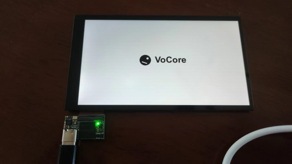
  1. Startup LOGO
  2. 60FPS at partily draw, 33FPS at full draw(5inch).
  3. Partily draw mode.
  4. I2C external device(for LEDs and buttons).
  5. USB Type-C connection
  6. More current for screen backlight.
  7. OLED, round or strip shape screen support.
  8. Interface compatible with V7B version.
  9. support HMI like features.

PS: This upgrade mainly focuses on supporting more different types of screens, such as bigger screens, special shape screens, and high resolution screens. Without USB TypeC, the rest of the features are almost the same as the current V7B version. For example, for dashboard usage, nobody can find out the difference between 30FPS and 60FPS without a special exam device.

MPRO 5inch samples are open to order for public test, please email us sales(at)vocore.io for MPRO, its mass production version is same price as current 5inch version.

Explain and some notes about the features:

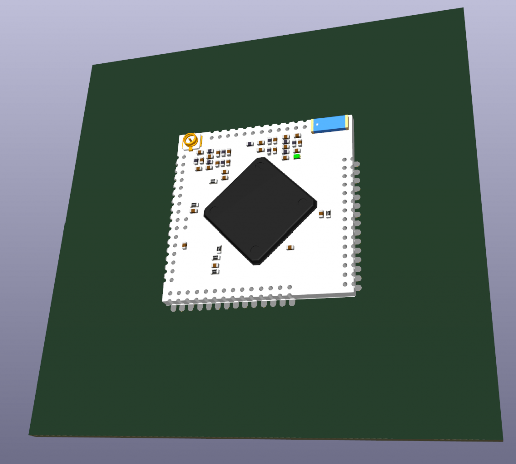
  • MPRO driver board size is 25.6mm x 15mm, it is 1mm more on top side than current V7B driver board(25.6mm x 14mm), this size change might effect shell/enclosure design.
  • MPRO screens are not compatible with V7B screens, so they can not replace each other.
  • Startup logo is an embed logo store inside driver board, once power on it will show on the screen.
  • Partily draw mode. We have this because USB2.0 only has limit speed for send pictures to screen, for small screen like our current 4inch, 5inch, it is no problem, but for bigger screen with high resolution like 10inch or more, full draw will low the frame rate a lot. So in order to reach 60FPS, we just modify the changed part on screen.
  • Dither for 16bits, with this feature, 16bits picture looks more smoothly. As I know Simhub already support this, so not very important for now.
  • I2C externel device. We have export I2C and one interrupt input for external buttons and LEDs. So with a simple MCU chip like CH32V003, we can control 512x WS2812B and 7×7=49 matrix buttons by USB through MPRO.
  • More current for screen backlight, means we can support bigger screens, thanks to USB TypeC, it can stand much more current than microUSB.
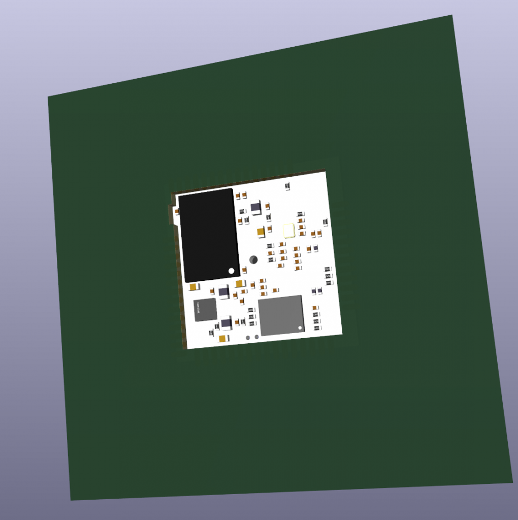
  • Interface compatible with V7B version. For MPRO version, we still have four USB test point at back of driver board which can also be used as SMT mount point. Also we have three more exported, I2C CLK, I2C DAT, I2C INT, so for developers can simply use them for external LEDs and buttons, do not need additonal Arduino and USBHub anymore.
  • For public test stage, I2C feature is still under develop and test, it will be release later by upgrade firmware.
  • V7B version 4inch and 4.3inch will update and replace at Mar.2024 or later if current 5inch test is good. Old version V7B will keep production for exists project, but it might have a longer lead time(6~8 weeks) to reach factory MOQ.
  • 5inch new version is now stable (Jan.1, 2024), V7B version is end of life, do not recommend for new design.

VoCore2: TeraTerm fix brick

For Windows user, a good kermit terminal is not easy to find, we suggest to use TeraTerm.

TeraTerm download link: https://github.com/TeraTermProject/osdn-download/releases

Reference to vocore.io/v2.html or vocore.io/v2u.html, we use TTL to upgrade firmware if the uboot is still alive.

Hardware part, need to connect USB2TTL device RX and TX to VoCore2 TXD2 and RXD2, then we you power on VoCore2, you will able to read something from serial port. Serial port parameter for VoCore2 UART2 is 115200, 8n1.

First, open TeraTerm, select COM5(or COM3, it is kind of random depends on your Windows system)

Second, setup serial port at Setup => Serial Setup

Third, at bootup, select 0 for serial port upgrade firmware.

Then, choose the firmware(it is sysupgrade firmware from openwrt)

ready to choose your firmware.
choose your firmware from TeraTerm menu File => Transfer => Kermit => Send
Now, start transfer the firmware file to VoCore2 memory, it normally takes from 5min to 20min, depends on the firmware size.
After transfer done, VoCore2 will automaticlly write to flash, do not power off VoCore2, or you have to do everything again.

If everything works normal, check the boot up Linux Log, you will see it has upgrade to the new firmware. 🙂

Screen: I2C to Drive RGB LEDs 2

More example code to use I2C on VoCore Screen driver board. These i2c function should be easier to understand and use.

int v2s_i2c_read_reg16(uint8_t addr, uint16_t reg, uint8_t *d, uint8_t size)
{
    uint8_t buf[64] = {0};
    int r;

    if (size > 58)
        return -1;         // required data is too much.

    buf[0] = addr;         // i2c device address
    buf[1] = sizeof(reg);  // write 2 bytes for register.
    buf[2] = size;         // read data size.
    buf[3] = reg >> 8;     // i2c device register high byte.
    buf[4] = reg & 0xff;   // i2c device register low byte.

    // send data to device i2c buffer.
    r = libusb_control_transfer(h, 0x40, 0xb5, 0, 0, buf, 5, 100);
    if (r < 0)
        return r;

    // trigger write to device, must send same device address.
    r = libusb_control_transfer(h, 0xc0, 0xb6, 0, 0, buf, 1, 100);
    if (r < 0)
        return r;

    // trigger read from device, first byte need to be the address.
    r = libusb_control_transfer(h, 0xc0, 0xb7, 0, 0, buf, size + 1, 100);
    if (r < 0)
        return r;

    memcpy(d, buf + 1, size);
    return size;
}

int v2s_i2c_write_reg16(uint8_t addr, uint8_t reg, uint8_t *d, uint8_t size)
{
    uint8_t buf[64] = {0};
    int r;

    if (size > 58)
        return -1;         // required data is too much.

    buf[0] = addr;
    buf[1] = sizeof(reg) + size;  // write 2 bytes for register and rest for data.
    buf[2] = 0;            // read data size.
    buf[3] = reg >> 8;     // i2c device register high byte.
    buf[4] = reg & 0xff;   // i2c device register low byte.

    memcpy(buf + 5, d, size);

    // send data to device i2c buffer.
    r = libusb_control_transfer(h, 0x40, 0xb5, 0, 0, buf, 5 + size, 100);
    if (r < 0)
        return r;

    // trigger write to device, first byte need to be the address.
    r = libusb_control_transfer(h, 0xc0, 0xb6, 0, 0, buf, 1, 100);
    if (r < 0)
        return r;

    return size;
}

Screen: Firmware Upgrade

VoCore Screen normally do not need to modify the firmware and we are not recommend to do that either, because upgrade firmware is pretty risk that possible lock the driver board cause it totally bricked and will not bring any benifit — no speed increase or function change. But sometimes, the driver board have to write firmware again, like in Windows it shows “Unknown device” and VID=04B4&PID=8613. Once this happens, we have to reload the firmware and try to fix it.

For Linux, it is easy to upgrade, download our eeprom upgrade application here: https://vocore.io/misc/eeprom.linux.zip, and run “sudo ./eeprom.u64”, select the correct firmware type which must match the screen type printed on screen back side. It depends on libusb, so need to install libusb first.

For Windows, that is not easy, because Windows do not have common USB driver, we need to install many driver for different VID/PID devices. I think we can use Cypress USB FX2LP tools which from the chip provider to do the work. I will check and try to find some easy way to do it for windows users. Currently you can try to use this one: https://vocore.io/misc/eeprom.win32.zip. Upgrade firmware for a normal VoCore screen will only bring risk to brick it but no benifit, so recommend never use it if not necessary.

When you use eeprom.exe, you can choose the correct firmware from the list. But it will require you install at least two libusb drivers by using zadig, one for 04b4:8613; one for 1004:c872; once installed them, eeprom.exe can work normal. screen_test.exe only need 1004:c872.

install driver by zadig for 04b4:8613 to use eeprom.exe

VoCore2: KiCAD7 Symbol & Module

For easy develop, the VoCore2 3d module and SMT footprint is upgraded to support KiCAD7, have fun 🙂

Consider SMT footprint has better yield rate for mass production, recommend to use this footprint.

Download STEP file at: http://vonger.cn/misc/vocore2/vocore2.3d.stp.zip or https://vocore.io/v2.html

Download Symbol at: http://vonger.cn/misc/vocore2/vocore2.smt.zip or https://vocore.io/v2.html

PS: also we have tape package. Contact us if you need this special package.

VoCore2: Get Chip Internal Temperture

For mediatek wifi driver, we can get the internal temperture by command “iwpriv ra0 stat | grep CurrentTemperature”, for example

root@OpenWrt:~# iwpriv ra0 stat | grep Temp
CurrentTemperature              = 73

For open source wifi driver, we can get temperture by user level driver (need to enable /dev/mem) source code here: https://github.com/Vonger/vocore2/tree/master/utils/mt7628tool

VoCore2: Compile Official UBOOT

To make your customized official uboot or our standard uboot, it requires two steps.

  1. Download latest uboot source code from https://github.com/u-boot/u-boot/tags, normally I choose the stable version who is not end with rc.
  2. Use our config file from https://github.com/Vonger/vocore2/blob/master/uboot/vocore2_defconfig, replace u-boot-2023.04/configs/vocore2_defconfig, then you can use make menuconfig to choose the option you want.

optional: for simple, after replace vocore2_defconfig, you can directly call make vocore2_defconfig, then call CROSS_COMPILE=mipsel-openwrt-linux- make, it will generate uboot by the default config.

PS: new version uboot compile size over 192KB, need to reduce…unselect Network Support it works. And customize uboot has some risk to brick your VoCore, better to have at least two VoCore or SPI flash loader to unbrick it if anything goes wrong. Check here vocore.io/v2.html, Unbrick VoCore2 part.

VoCore2: Official UBOOT Upgrade Firmware

Official uboot is very different from the mediatek uboot, not that easy to use but very flexible.

For example, if my firmware stored in USB disk and I want to update firmware from uboot, I will need to load from usb disk to memory first, then erase flash and write to it all by command.

  1. usb start this will enable usb
  2. fatload usb 0:0 0x81000000 root_uImage my firmware name is root_uImage, and I load it to 0x81000000 (DDR memory address)
  3. sf start this will enable spi flash
  4. sf erase 0x50000 0xfb0000 erase the firmware partition, from 0x50000 and size is 0xfb0000
  5. sf write 0x81000000 0x50000 0x600325 read from 0x81000000 and write to SPI flash 0x50000, size is 0x600325(6292261), this size we can find at fatload.

Here is the log:

U-Boot 2022.01 (Oct 29 2022 - 14:39:20 +0000)                                   
                                                                                
resetctl_reboot resetctl-reboot: set_state_simple op missing                    
mtmips-reset rstctrl@0x34: set_state_simple op missing                          
CPU:   MediaTek MT7628A ver:1 eco:2                                             
Boot:  DDR2, SPI-NOR 3-Byte Addr, CPU clock from XTAL                           
Clock: CPU: 580MHz, Bus: 193MHz, XTAL: 40MHz                                    
DRAM:  128 MiB                                                                  
pinconfig pin_state: set_state_simple op missing                                
simple_bus palmbus@10000000: set_state_simple op missing                        
mt7628-clk clkctrl@0x2c: set_state_simple op missing                            
mt762x_wdt watchdog@100: set_state_simple op missingg                           
WDT:   Started watchdog@100 with servicing (60s timeout)                        
MMC:   fixed_clock clk48m@0: set_state_simple op missing                        
pinconfig sd_iot_mode: set_state_simple op missing                              
mmc@10130000: 0                                                                 
Loading Environment from SPIFlash... mt7621_spi spi@b00: set_state_simple op mig
mt7621_spi spi@b00: spi_find_chip_select: plat=86fa0258, cs=0                   
jedec_spi_nor spi-flash@0: set_state_simple op missing                          
SF: Detected w25q128 with page size 256 Bytes, erase size 4 KiB, total 16 MiB   
jedec_spi_nor spi-flash@0: from 0x00030000, len 4096                            
OK                                                                              
In:    uart2@e00                                                                
Out:   uart2@e00                                                                
Err:   uart2@e00                                                                
Net:   pinconfig ephy_iot_mode: set_state_simple op missing                     
mtmips-reset rstctrl@0x34: set_state_simple op missing                          
                                                                                
Warning: eth@10110000 (eth0) using random MAC address - ce:78:14:4e:a5:ac       
eth0: eth@10110000                                                              
Hit any key to stop autoboot:  0                                                
=>                                                                              
=> usb start                                                                    
starting USB...                                                                 
Bus ehci@101c0000: ehci_generic ehci@101c0000: set_state_simple op missing      
mt76x8_usb_phy usb-phy@10120000: set_state_simple op missing                    
USB EHCI 1.00                                                                   
scanning bus ehci@101c0000 for devices... usb_hub usb_hub: set_state_simple op g
2 USB Device(s) found                                                           
       scanning usb for storage devices... 1 Storage Device(s) found            
=> fatload usb 0:0 0x81000000 root_uImage                                       
6292261 bytes read in 245 ms (24.5 MiB/s)                                       
=> sf start                                                                     
No SPI flash selected. Please run `sf probe'                                    
=> sf probe                                                                     
mt7621_spi spi@b00: spi_find_chip_select: plat=86fa0258, cs=0                   
mt7621_spi spi@b00: spi_find_chip_select: plat=86fa0258, cs=0                                                                                                   
=> sf erase 0x50000 0xfb0000                                                    
jedec_spi_nor spi-flash@0: at 0x50000, len 16449536   
SF: 16449536 bytes @ 0x50000 Erased: OK
=> sf write 0x81000000 0x50000 0x600325
device 0 offset 0x50000, size 0x600325
jedec_spi_nor spi-flash@0: to 0x00050000, len 6292261
SF: 6292261 bytes @ 0x50000 Written: OK

Screen: Dashboard Solution

Because Simhub makes it very easy to DIY a dashboard for sim racers, many people ask about tech support for DIY projects with VoCore screens. This tutorial will help you choose the parts.

To complete a dashboard, the easiest way is to use existing solutions. The most common one is to use Arduino to control the LEDs, with open-source code that can be found at SimHub; use VoCore as the dashboard display; and use a USB hub to connect everything together.

It seems pretty simple, but there are a few things to consider:

  1. USB cable. This is very important because the VoCore screen operates at a maximum USB speed of 480MHz. This high speed requires cables designed for high-speed data transfer rather than just charging, or it will not work. Additionally, when DIYers create their own PCBs, they need to carefully match the trace impedance to 90 ohms for the two USB data cables and keep them as short as possible. Failing to do so may cause the VoCore screen to work unstably, sometimes misaligning or frequently disconnecting from the PC.
  2. USB hub. This is another important part, and it is recommended to use MTT (Multiple Transaction Translators). This is because Arduino is a slow device that works at 12MHz, while the VoCore screen operates at 480MHz. Normally, if you only use one VoCore screen and one Arduino, STT (Single Transaction Translators) should work as well, but MTT will provide better performance.
  3. Power supply. The VoCore screen typically consumes around 300mA of current, while Arduino requires up to 100mA (or more if you use additional LEDs), and the USB hub uses around 50mA. Make sure your solution can provide enough power for all components. A standard USB port outputs around 500mA, which is sufficient for most uses. However, if you have more LEDs (each consuming about 20mA), the total power consumption may exceed 500mA, causing instability in the entire solution. In such situations, it’s better to use a USB 3.0 port, which can output 1000mA.

That’s all for now. If there’s anything else to consider, I will update this blog. Have fun with your DIY dash! 🙂

VoCore2 Screen: Run on RaspberryPi

Prepare System

sudo apt update && sudo apt upgrade -y
sudo apt install raspberrypi-kernel-headers build-essential -y
sudo reboot

Download & Compile & Install Driver

git clone https://github.com/Vonger/vocore2 # download code
cd vocore2
cd utils/fbusb/src
make -C /usr/src/linux-headers-`uname -r`/ M=`pwd` modules # compile
sudo mkdir -p /lib/modules/`uname -r`/extra
sudo cp fbusb.ko /lib/modules/`uname -r`/extra/ # install module
sudo depmod -a # load at bootup

Install XORG Configuration File

sudo cp /etc/X11/xorg.conf /etc/X11/xorg.conf.bak
sudo nano /etc/X11/xorg.conf

Paste the code to the end of the file.

Section "Device"
	Identifier      "vocore screen"
	Driver          "fbturbo"
	Option          "fbdev" "/dev/fb0"

	Option          "SwapbuffersWait" "true"
EndSection

Ready to Use

  1. plugout hdmi cable
  2. connect vocore screen
  3. reboot raspberrypi board
  4. the graphic will display on vocore screen by default (test on rpi4)

Here is a video about the performance.