I should get my new v0.5 PCB board today, but because of the holiday of May.1, I have to wait three days more. I am patient 🙂
The software part should be stable, has run almost 10 days without a mistake. Unfortunately, the road of Taiyuan is under repairing…my power is cut off this morning, so I can not capture new picture for uptime or continue my stable test.
For the hardware part, I will do three tests.
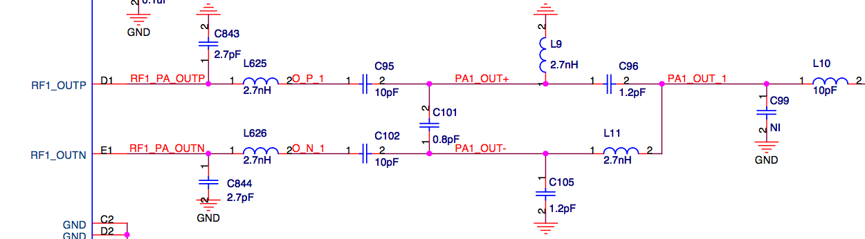
1. replace 1.2nF to 0.1uF.
90% routers and even raspberrypi are using 0.1uF for the ethernet circuit part, but all MTK/Ralink routers are using 1.2nF or 1nF. Why? That is for ethernet signal, so I think it do not have relation with RT5350 chip. I will test and compare, then the truth will soon be revealed to the world 🙂
RT5350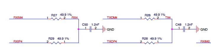
AR9331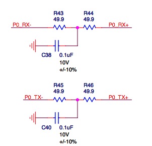
RaspberryPi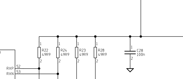
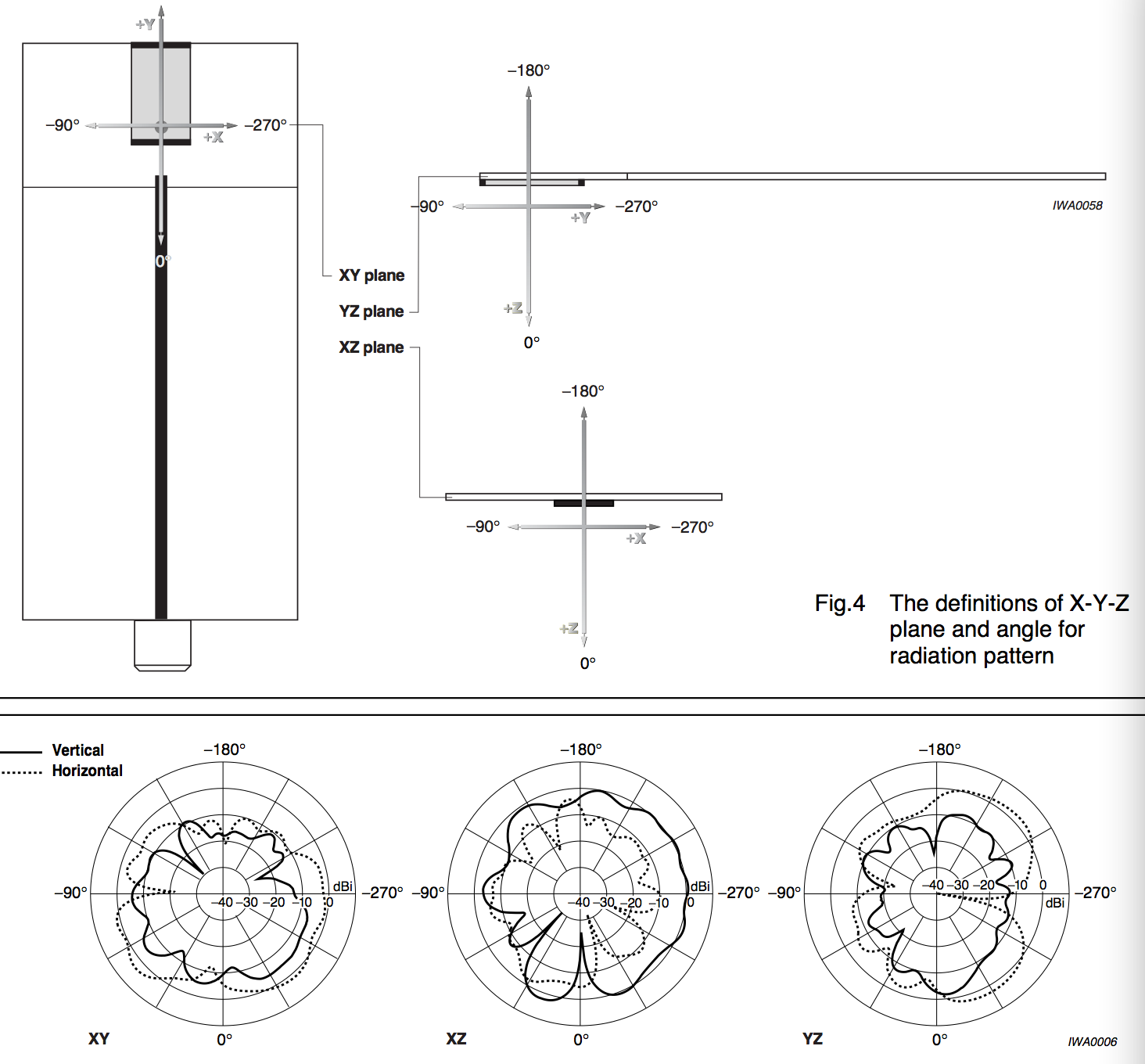
2. on board ceramic antenna.
I have tried my best to leave 5.5mm clearance zone for that ceramic antenna, if its performance is too low(<60% 4dBi IPX antenna), I will remove it. Maybe more clearance zone will be better but need to test.
from CAN4311153002451K manual:
3. 22nF to 0.1uF, 4.7uF to 1uF, 1.5pF to 1.2pF
on my board, C8,B5,A5,B3,C9 connected to 22nF, that should be used to make wifi part 1.2V stable, so change it to 0.1uF should be better, but might effect signal, need to test.
on my board I have seven 4.7uF, I do not think that is necessary. This board size is very small, and already have two super big 22uF to stable its power on 3.3V. Replace 4.7uF to 1uF should be acceptable.
on antenna part, 1.5pF(+/-0.25pF) is almost same as 1.2pF(+/-0.25pF), so why use one more capacitance type?
AR2317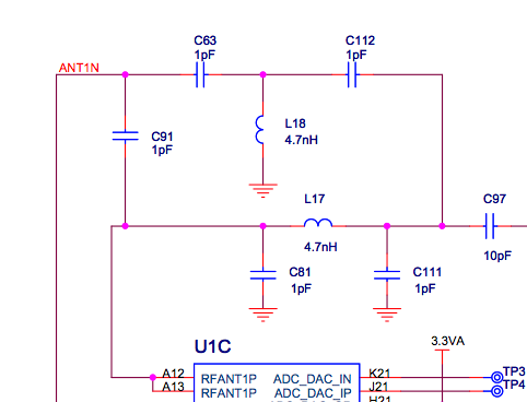
MT7620A