Monthly Archives: April 2014
Dock for VoCore v0.5
VoCore v0.3 is not that easy to test, so I make a dock for v0.5.
Its size is 2.5×2.5×1.6. Once connect it to VoCore v0.5, the total size of the two will be 2.5×2.5×2.0.
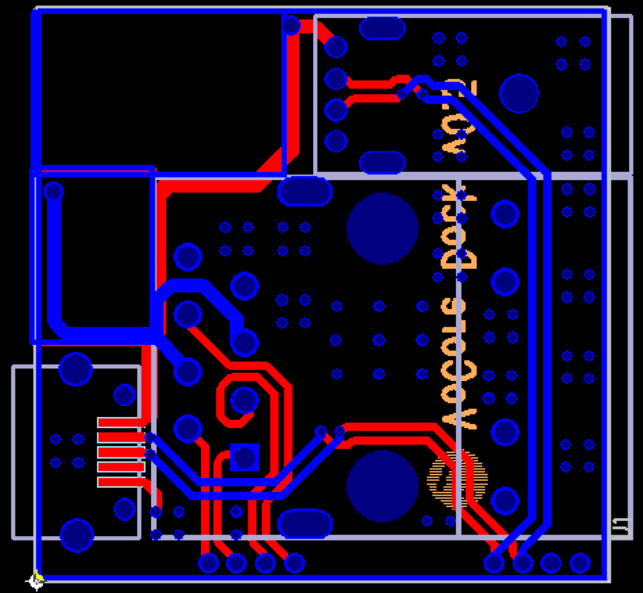
This dock contains three parts.
A: USB1(left bottom) is used for power +5.0V, it should be connected to USB power.
B: USB2(top right) is a full function USB.
C: RJ45(right bottom) is for WLAN/LAN connection, connected to EPHY_P0.
It is not the final version of the dock.
From Apr.23, I kept one of my board running. 🙂
![]()
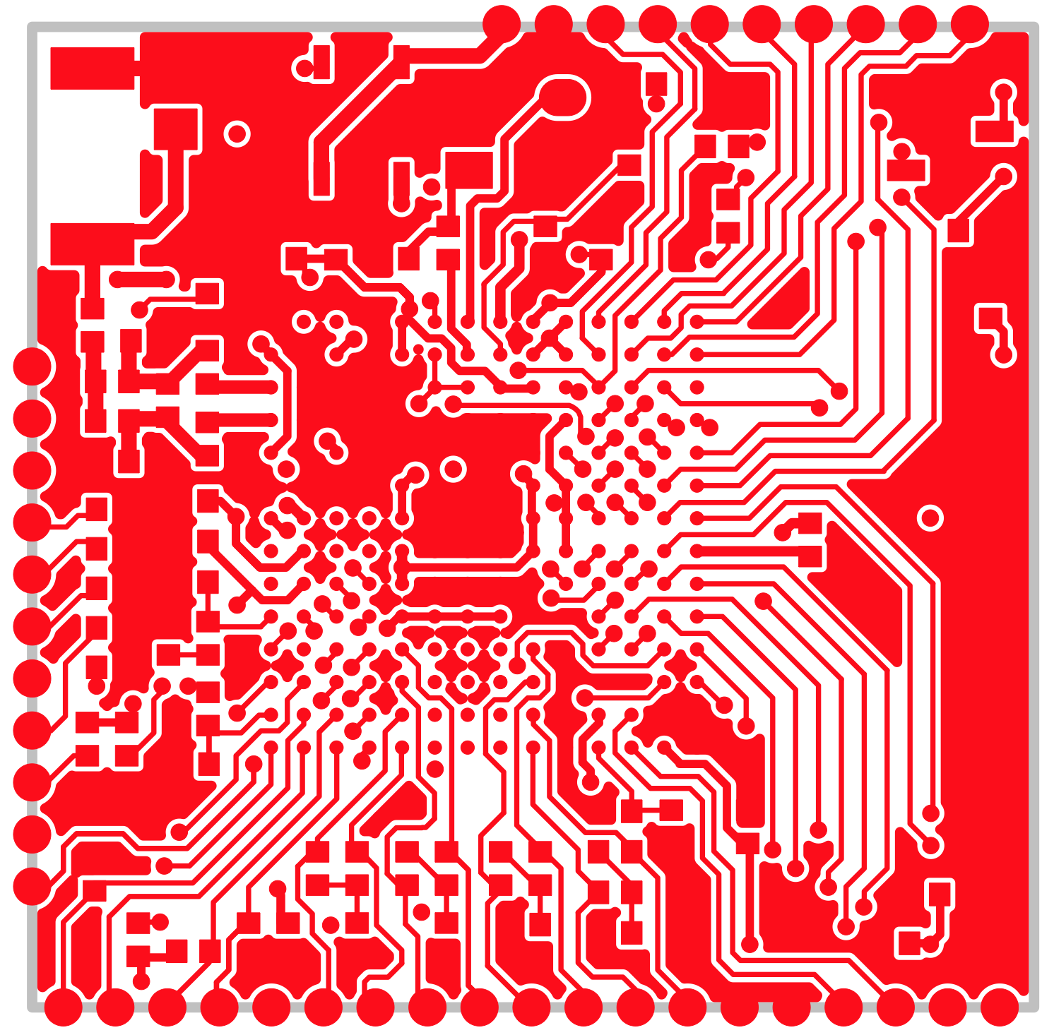
Antenna Circuit Design For VoCore Part 1
I am a newbie on antenna, after study a lot from internet, get some knowledge about it.
PCB board is 1mm, composed by 9 layers:
1. Top Solder Mask      ==> 0.5mil
2. Top Copper           ==> 1.35mil(1oz)
3. PP 7628              ==> 7mil
4. Inner Copper         ==> 1.35mil
5. Main                 ==> 20mil
6. Inner Copper         ==> 1.35mil
7. PP 7628              ==> 7mil
8. Bottom Copper        ==> 1.35mil
9. Bottom Solder Mask   ==> 0.5mil

Total: about 40mil
PP7628 DK=4.2~4.7(4.7,<1GHz), use 4.3 for 2.4GHz. width=13mil, Z=49~50ohm, ceramics antenna Z=50ohm, perfect matched. So after this calculation, I changed board height from 0.8mm to 1mm and use line width 13mil for antenna.
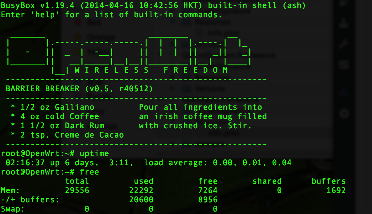
VoCore Passed 72 Hours Test
From Apr.15~Apr.18, I kept it run “top” on the board and every 5 minutes my script sent one test.bin file(about 2MB) to board /tmp/ folder through wifi.
Now after 72 hours, its free memory is 6.5MB compared to 9.9MB at startup. Its temperature is about 65C at end(house about 24C) without heat sink. Looks good for me. 🙂
About WRTnode :) RT5350 vs MT7620
看来最近开源硬件确实挺火,深圳的创客们搞出来个WRTnode,基本理念和我不谋而合。我们用的都是OpenWrt系统,这样软件都可以共用。
其实我开始时也想用MT7620做设计,但是我最后由于以下几点原因否决了。
1.成本高,芯片是RT5350的一倍多,内存芯片价格也略高。
我希望做开源的东西,能以最低的门槛,做最大众化的东西。记得十年前,我上大学时从淘宝买到一块60块钱的二手8051实验板时的快乐,希望这样的快乐能更多的传递下去。
2.用的是DDR2,线很难布。
DDR2的频率比较高(>200MHz),MT7620在内存和芯片间需要匹配阻抗。这样就导致了板子不能做的小,而且由于阻抗的存在,成本也会难以控制。WRTnode做到了40×30,虽然没有VoCore小,但我相信这基本是MT7620的极限了,而VoCore则不然,如果舍得成本,换成BGA封装的SDRAM内存,体积和功耗还可以进一步减小。
3.多余的性能性价比不高。
多余的CPU性能比较鸡肋,360MHz足够处理应用,580MHz实际性能比它快不了多少,基本可以说360MHz干不了的580MHz也干不了。
DDR2速度没有用处,瓶颈在总线速度上,不能完全发挥DDR2的速度。
WRTnode的优势:
1. 功耗低,MT7620运行电流是140mA左右,RT5350是200mA,同时带来的好处是发热大大减小。我粗略计算一下,考虑到多种因素,MT7620比RT5350节能20%~30%.
2. 速度快,MT7620的CPU可以运行在580MHz, RT5350是360MHz。
3. 支持内存大,MT7620的DDR2单片最小都是64MB,而SDRAM最大只有32MB,64MB还得接两片。
4. 双天线设计,这个真的很好,可以发挥出802n的最大威力,必须赞。
VoCore的优势:
1. 价格便宜,成本只有MT7620解决方案的1/2到1/3.
2. 体积小,体积只有WRTnode的三分之一,WRTnode核心板5×4.5=22.5平方厘米,VoCore是2.4×2.45=5.88平方厘米.
3. 容易扩展,GPIO多,导出了RT5350所有的GPIO,一共22个,还有JTAG,USB,I2C,I2S,PCM,网线,串口,一个都不少.
4. 支持多种电源电压,用3.3V~6V供电都可以,可以方便的使用锂电池供电不需要转换.
WRTnode设计上值得我学习的:
1. 导出了SPI的接口。
这个设计我没有考虑到,有这个接口确实很方便,省了60块买flash刷写夹具的钱。
这个是夹具链接,给他们做个广告http://item.taobao.com/item.htm?spm=a230r.1.14.1.6HxkOH&id=36799806985&_u=f40cgkm9c63
2. 接口都是2mm的插孔
我做出了24mm的半孔版后,觉得半孔虽然减小了很大的体积(0.5平方厘米),但是焊接,接插都很不方便,很容易把半孔铜皮弄坏。2mm的插孔只要插上标准的杜邦线就行了,适合做实验。在下一版我会改进,使用完整插孔,由于板子面积有限,使用标准间距1.27mm,做下来的板子应该是990milx990mil(25.146mm)=6.33平方厘米
WRTnode我要吐槽的:
1. 导出的网线太多了。
这是做智能设备控制又不是做路由,把5个网线接口都导出来,至少两个口基本一辈子都不会用到。平空增加布线复杂度。这样可能会不得不在中间电源层布线,而这样的布线会对信号层有很大干扰,特别是DDR2本来就是高频,网线口的速度也是100MHz以上的,这样的板子可能会不稳定。我在做5350的时候虽然最高只有166MHz也是小心翼翼的,绝不敢在电源层走线(别看VoCore小,只在top和bottom走线),高频尽量3W实在不行2W。串扰模拟时按1GHz,3.3V得出最大串扰电压<100mV,应该还算稳定。
2. 买不到……
这板子想搞个研究下,可惜哪都没卖的,是卖的太好么……郁闷,不过淘宝上其他的MT7620的开发板倒是很多。
最后,好久没有写中文博客,多说一句:
我坚信,不远的未来我们只需要通用的硬件,而功能都由软件实现。VoCore就是为了实践此而诞生的。
Wifi is not working on two of my boards 5(final)
That problem is confirmed, it is caused by “factory setting” area(0x00040000-0x00050000).
I get the bug flash and normal flash, compare the two, get the following result.
BUG BOARD:
< 00040000  FF FF FF FF FF FF FF FF  FF FF FF FF FF FF FF FF
< 00040020  FF FF FF FF FF FF FF FF  FF FF FF FF FF FF FF FF
< 00040030  FF FF FF FF FF FF FF FF  FF FF FF FF FF FF FF FF
< 00040040  FF FF FF FF FF FF FF FF  FF FF FF FF FF FF FF FF
< 00040050  FF FF FF FF FF FF FF FF  FF FF FF FF FF FF FF FF
< 00040070  FF FF FF FF FF FF FF FF  FF FF FF FF FF FF FF FF
< 000400D0  FF FF FF FF FF FF FF FF  FF FF FF FF FF FF FF FF
< 000400E0  FF FF FF FF FF FF FF FF  FF FF FF FF FF FF FF FF
< 00040120  FF FF FF FF FF FF FF FF  FF FF FF FF FF FF FF FF
NORMAL BOARD:
> 00040000  50 53 00 01 00 0C 43 30  50 C8 FF FF FF FF FF FF
> 00040020  FF FF FF FF FF FF FF FF  00 0C 43 30 50 77 00 0C
> 00040030  43 30 50 66 11 FF 24 28  FF FF 2B 01 55 77 A8 AA
> 00040040  8C 88 FF FF 0C 00 00 00  00 00 00 00 00 00 FF FF
> 00040050  FF FF 0A 0A 0A 0A 0A 0A  0A 0A 0A 0A 0A 0A 0B 0B
> 00040070  FF FF FF FF FF FF 03 80  FF FF FF FF FF FF FF FF
> 000400D0  FF FF FF FF FF FF FF FF  FF FF FF FF FF FF 66 66
> 000400E0  CC AA 88 66 CC AA 88 66  CC AA 88 66 CC AA 88 66
> 00040120  81 09 1C 13 4F 15 4F 15  03 1D 07 1D FF FF FF FF
I guess this data(about 512 bytes) should be same data format in EEPROM. The bug one can not load mac address because in this area it is all invalid/empty(0xFF).
I am right again:
this is EEPROM from RT5350 official SDK.(0xFF lines deleted, 512bytes)
ADDRESS   +0 +1 +2 +3 +4 +5 +6 +7  +8 +9 +A +B +C +D +E +F
00000000  50 53 00 01 00 0C 43 30  50 58 FF FF FF FF FF FF
00000020  FF FF FF FF FF FF FF FF  00 0C 43 30 50 77 00 0C
00000030  43 30 50 66 11 FF 24 28  FF FF 2B 01 55 77 A8 AA
00000040  8C 88 FF FF 0C 00 00 00  00 00 00 00 00 00 FF FF
00000050  FF FF 0A 0A 0A 0A 0A 0A  0A 0A 0A 0A 0A 0A 0B 0B
00000070  FF FF FF FF FF FF 03 80  FF FF FF FF FF FF FF FF
000000D0  FF FF FF FF FF FF FF FF  FF FF FF FF FF FF 66 66
000000E0  CC AA 88 66 CC AA 88 66  CC AA 88 66 CC AA 88 66
00000120  03 09 1C 13 4F 15 4F 15  03 1D 07 1D FF FF FF FF
This is another EEPROM in SDK.
ADDRESS   +0 +1 +2 +3 +4 +5 +6 +7  +8 +9 +A +B +C +D +E +F
00000000  50 53 00 01 00 0C 43 30  50 58 FF FF FF FF FF FF
00000020  FF FF FF FF FF FF FF FF  00 0C 43 30 50 77 00 0C
00000030  43 30 50 66 11 FF 24 30  FF FF 2B 01 55 77 A8 AA
00000040  8C 88 FF FF 0C 00 00 00  00 00 00 00 00 00 FF FF
00000050  FF FF 0A 0A 0A 0A 0A 0A  0A 0A 0A 0A 0A 0A 0B 0B
00000070  FF FF FF FF FF FF 03 80  FF FF FF FF FF FF FF FF
000000D0  FF FF FF FF FF FF FF FF  FF FF FF FF FF FF 66 66
000000E0  CC AA 88 66 CC AA 88 66  CC AA 88 66 CC AA 88 66
00000120  03 09 1C 13 4F 15 4F 15  03 1D 07 1D FF FF FF FF
So, the factory setting is necessary and important, looks like some driver are reading that when the board boot up.
After copy 512 bytes data to its location at flash 0x00040000, everything works again. 😀
Wifi is not working on two of my boards 4
I find the problem…That is system problem.
After I update openwrt back to old version, all my five bug boards work well. T-T, spend me a lot of time to catch that bug.
That is why my first board work. I think after I copy openwrt to my first board I just run “git pull & make”…
But on the log, both of them are OpenWrt R39957. So it is not version problem. HWAddr is load from FLASH factory area, maybe it is that problem. If I erase the flash, all data will set to 0xFFFFFFFF, same as the wrong HWAddr FF:FF:FF:FF:FF:FF. Just a guess, need time to check.
VoCore v0.3 for Sale
Today I opened one taobao shop, address is http://item.taobao.com/item.htm?id=38275419692.
These modules are soldered by myself , some of them are not very stable yet. That taobao shop is just used to send to my friends for test.
Only five of them 🙂 But I promise once the test is done, there will be more.
VoCore Output Interface
VoCore v0.3~v0.4:
TOP (from left to right)
PN03: +3.3V~+6.0V(USB +5.0V or Li-Battery 3.7V), POWER
PN04: GND, POWER
PN05: B11, JTAG_TDO, GPIO
PN06: A11, JTAG_TRST_N, GPIO
PN07: A12, JTAG_TCLK, GPIO
PN08: A13, JTAG_TMS, GPIO
PN09: B12, GPIO0
PN10: A14, JTAG_TDI, GPIO
PN11: B13, I2C_SD, GPIO
PN12: B14, I2C_SCLK, GPIO
LEFT (from top to bottom)
PN23: +1.8V, OUTPUT POWER, max 600mA
PN22: J4, DCD_N, UARTFULL, GPIO
PN21: K4, CTS_N, UARTFULL, GPIO
PN20: K3, EPHY_LED0, GPIO, GPIO
PN19: K2, TXD, UARTFULL, GPIO
PN18: L1, EPHY_LED1, GPIO
PN17: L3, DSR_N, UARTFULL
PN16: L4, EPHY_LED2, GPIO
PN15: M1, EPHY_LED3, GPIO
PN14: M3, RIN, UARTFULL, GPIO
PN13: M4, EPHY_LED4, GPIO
BOTTOM (from left to right)
PN24: N2, TXD2, UARTLITE, GPIO
PN25: P2, RTS_N, UARTFULL, GPIO
PN26: N3, RXD, UARTFULL, GPIO
PN27: P3, RXD2, UARTLITE, GPIO
PN28: N4, DTR_N, UARTFULL, GPIO
PN29: N5, EPHY_TXN_P0
PN30: P5, EPHY_TXP_P0
PN31: M5, EPHY_RXP_P0
PN32: L5, EPHY_RXN_P0
PN33: P9, EPHY_RXP_P4
PN34: L9, EPHY_TXP_P4
PN35: N9, EPHY_RXN_P4
PN36: M9, EPHY_TXN_P4
PN37: GND, POWER
PN38: GND, POWER
PN39: N12, UPHY0_PADM, USB
PN40: P12, UPHY0_PADP, USB
PN41: +3.3V, POWER
PN42: +3.3V, POWER
Power must connect to PN03/PN41&PN42. PN03 input voltage is +3.3V~6.0V, PN41/PN42 is 3.3V. If PN03 is connected, PN41/PN42 is able to output +3.3V power, current is about 500mA(3.3V->PN03), 750mA(5.0V->PN03).
New simple file transfer application for LAN
I find it is very tedious when I send file from my pc to my board.
The shortest command is scp, but it is not short.
I have to write something like this:
scp 192.168.x.x:someplace/somefile ./somefile
then, input password every time.
I hate that, it is a waste of time.
Another problem is it is hard to transfer file from my windows pc to that board or my linux pc… Best way is to use ftp, but on my board the memory is limited and precious, ftpd will take a lot of memory and never return them. I need some cross platform tools.
So after some struggle, I write a simple application. I called it “wolf”. 🙂 And its real name is vof.
To send one file, it is easy to use:
vof ./somefile
it will show four number code, such as “1234”.
and to get this file, just call this command on the other pc:
vof 1234
then the file is copied into that position through local network safely.
source code: http://vonger.cn/upload/vof.c
linux(x86): http://vonger.cn/upload/vof.unx
linux(mips):http://vonger.cn/upload/vof.voc
macos(x86):http://vonger.cn/upload/vof.mac
windows(x86):http://vonger.cn/upload/vof.exe
memory check:
macos: 308KB
windows: 1.6M
linux(x86): 0.2M
linux(mips): 116KB(without upx compress: 88KB)
openwrt do not support get memory usage, just used a trick, run vof, then call “free” or “cat /proc/meminfo”, kill vof then call “free” again, one is 10888KB, one is 11004KB, so vof takes about 116KB.